 Deutsche Version
| I. Introduction - The Beam and I |
II. Lasers homebuilt in most parts
|
III. Commercial lasers, heads, tubes (mainly argon)
|
| IV. Diane's Laser Collection (17 pic's) |
| V. Links |
Childhood dreams came to an end. No, to be honest, they only slept until
I was in the final High School classes. It was the beginning 80ies, and being
a frequent reader of the german issue of Scientific American, one day I found
the famous description of the mercury laser in it.
Huh? A guy somewhere out there built his OWN laser?
The feaver came back again. When he could do it, I also can do it, I decided.
However, I knew a lot more about physics than before, also liked to spent time
with the school's little HeNe laser (on rare occasions). Got a basic knowledge
of what is important for lasers to become working.
A few telephone calls made me quite unhappy. I had learned you can get all the
stuff you need if you really want - and can pay the prices. HIGH prices. Again
there was the "ruby problem": lasers are *expensive*.
"Silly, one cannot have one's own laser", a fellow laughed about me, "that's
only for laboratories." I better didn't tell him about my desire.
So I thought: "One cannot? Let's see about that."
Don't ask me today why I started to study mathematics. We had a quite famous
Department of Quantum Optics on our university, perhaps I should have gone to
the laser business. But those days computers were still more exciting than
lasers to me, and that's it.
Now, being a student, I had access to real scientific literature, and I
learned a lot about the theoretics of lasers (and, reading the business laser
magazines, also about technical realisations). I studied various descriptions
of laser types and decided to try about a flaslamp pumped dye laser. This one
at least needed no expensive ruby. :)
To make a sad story short, I learned a lot about how to blast stroboscope
tubes using a voltage doubler and really BIG capacitors, and I guess the
carpet in my room at the student's community will still have these nice pink
rhodamine spots. :(
I gave up on dyes.
But I still wanted a laser, and some more telephone calls brought a fine small
Siemens HeNe tube to me (it was a new 1.5 mW LGR7621). Shall I tell I heard
some of the wellknown "brzzzz's" from self-wound transformers until I looked
for a used neon transformer? Still a descent of my grandpa I was...
So I spent my time to built a casing for the transformer and a recitifier out
of a box of 1N4007's (never tell this a engineer student. I did, the poor boy
almost got a heart attack).
By the way, the LGR7621 is quite robust. One day I caused a short which
*detonated* the anode resistor (another lesson about BIG capacitors). After my
eyes had recovered from the resulting supernova inside the tube, I anxiously
looked if there's still anything alive. A visual inspection showed up a lot of
very small cracks along the inside of the bore. Replaced the mortal remains of
the blown resistor by a fresh one, it still started and lased! I used it for
years after this accident without significant drop. Brave little HeNe - see it
in "Diane's Laser Museum". :)
After some time, HeNe became boring to me. Using an internal mirror tube is
one task, to built a device like Scientific's mercury completely on your own
another. So I started some prepearing experiments in that direction for the
next time.
I got a simple vacuum pump and an unsealed neon tube and began to work with
glow discharges. To keep it short, I had to perform lots of experiments to
learn about vacuum, outgassing and purity of gasses. Over the years, my little
laboratory grew: a selfmade voltage doubler for the neon transformer, a
selfmade mercury vacuummeter, a better pump, noble gases in liter bottles, a
hand-held spectroscope, longer discharge tubes. To work, all this took years
of learning by doing.
Then the next strike came, of course again by Scientific American. It was the
copper vapor laser. How exciting... for I knew very well I had no experiences
about laser optics until now - but the superradiant copper lines would need
none. In words, I could start immediately.
But unlike the old days, I decided to study a bit about superradiant laser
before blindly begin to "hammer and saw". And by this I found out about the
still simpler N2 laser.
I decided to have one.
And in 91, a selfmade 10cm test tube of acrylic with quartz windows lased! I
danced in my room, for after 10 years I finally got it!
For the fact the 10cm tube lased quite weak I studied more about N2 laser
design. The major problem was, I could reach only 10 kV with my equipment thus
having poor energy densities in the discharge. Longer selfmade tubes also
lased weaker than expected (I tried several), even if attaching a metal mirror
to one end. I had to pinch the discharge somewhat, but doing this in a tube
made of acrylic would easily overheat and smoke the walls.
Those days I already worked for my Ph.D. thesis, and the research center where
I did it had the most precious thing I ever saw in a library: the COMPLETE
Review of Scientific Instruments. Complete means complete: from issue #1 of
1929. And after some hours with it, I found the most useful paper about N2
type gas lasers I know. It is about the "strip line" type laser using a
segmented discharge bore originally designed for the UV lines of the hydrogen
laser [1].
I adopted the design a bit to my power supply (shorter striplines, shorter
discharge segments) and pinched the discharge even more by adding short pyrex
capillaries inside the segments (see "The
Querflöte"). Believe me, it was a *lot* of work to drill
holes for 56 electrodes and fill in the pyrex tubes successivly from the end
of the outer acrylic tube. But finally I had a 3 mm x 98 cm bore with a nice
high energy density. For its strange appearance, I baptised it the "Querflöte"
- english "German
Flute".
The first thing I noticed after the first tests was, this baby would lase with
every gas containing a bit nitrogen, even dirty air. :) Mirrors were good for
nothing, and I easily got all three UV lines on a fluorescent screen using a
"water prism" (triangle pot glued together from thin pyrex pieces and filled
with water, which absorbs UV much less than a massive pyrex prism).
Of course I also tried other gases, and the green superradiant Ne line at
540.1 nm was strong in this tube, too. Over the time it became my favourite.
And on few occasions, after long times of green Ne, it was also possible to
get the much weaker orange line at 614.3 nm at a lower pressure. But normally
it dissappeared after some time from outgassing impurities. The still weaker
yellow line I never catched.
Impurities were what finally drove me tired. It was common for my "German
Flute" to be run with gas throughflow. Otherwise lasing stayed only for
seconds. On one occasion I tried a bore cleaning via He bombardement which
took several hours. But after finish, what I call the "dirt spectrum" (N2
band, H alpha line plus Hg lines -- mercury from the vacuummeter) reappeared
in half an hour.
Whenever I liked to start my laser, I had to spent days and hours in front
just for basic cleaning the vacuum devices. And, the cost for the needed
constant flow of Ne burned a hole in my pocket. Pure lab-grade neon isn't that
cheap.
And then, a few years later, I got a pen-sized red diode laser which made
roughly twice the output power of my homebuilt in the green. It was
depressing.
Sometimes in life one has crises and has to seperate from several things. So it was for me, and it was such a crisis which made me giving away a lot of things - including all my lasers. The university didn't take them (security reasons of course), but I found a physicist collecting strange devices, and I hoped my baby still has a home there (even if it doesn't lase any more). So, off I were.
Yes, I *was*. Some day I visited some friends, and I wondered to see a
yellow HeNe in their rooms. They told me to use it for illumination of large
naturally grown quartz crystals, for they like the "golden shattered glow" in
them doing so.
But they knew less to nothing about lasers, and I told about for an hour or
so. And thought about I also would like illuminated crystals. But not red or
yellow - green and blue, perhaps from an argon ion laser it would have to be.
In the days of internet it is an easy task to feed "argon laser" to google.de
and see what happens. So I found "Sam's Laser FAQ's", where a version of this
story now also is online.
The dream of an argon ion laser came true only recently (2007/2010) - these things for a long time were quite expensive, even
if used. DPSS lasers are much more simpler (amateur designs also)... meanwhile
I built one (2005). See Xenotim for details.
My first baby 2003 was 11 years old and its tube not any more in a good
condition, partly due to the storage at the physicist. Somewhere it outgassed
or leaked.
But in the end, I could not leave it alone at the shelf - it was my biggest and
most successfull laser. So in the beginning of 2006 I decided to restore it completely
(means rebuild of the bore, exchange of all seals and the blumlein dielectric, cleaning
and test of all else parts).
Finally...
"There's no such thing like a gas laser!"
And all else I try to build... I'll write about it from time to time here. :)
~D. N.
The pictures show the laser before the 2006 restoration; however, the changes wouldn't be
visible in any way.
Added to the vacuum supply was a second vacuum gauge (-1 to +1.5 bar) so the higher
pressure range can be measured in future experiments.
|
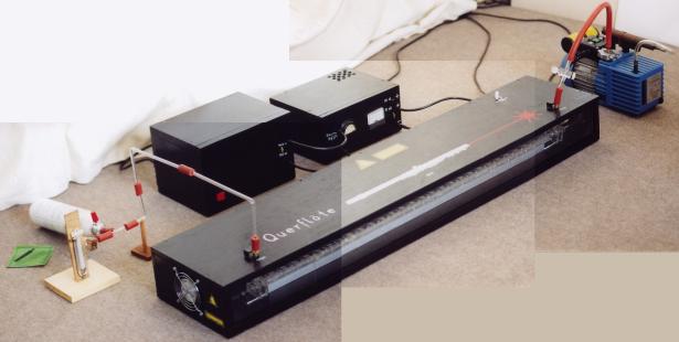
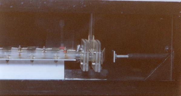
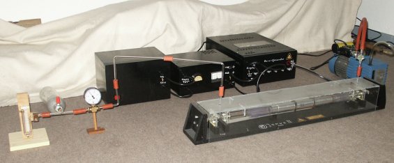
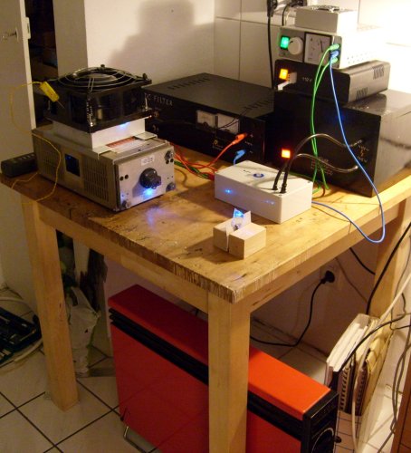
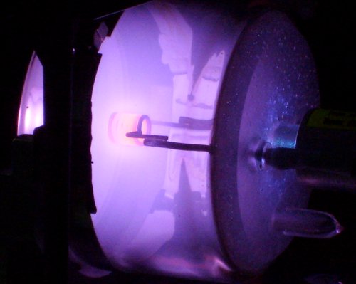
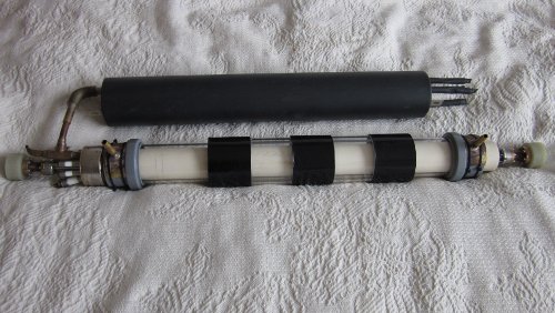
Picture 1 - Overall view of the "Querflöte" laser
(composed from three seperate exposures). Besides and behind the long laser head at the right end the rotary vacuum pump, in the back high voltage transformer and voltage doubler / rectifier, at the left end low-pressure gas can and mercury vacuum gauge. The laser head has a plexiglass front cover, so it is possible to watch the tube in operation. Hires version of picture (207 k) |
|
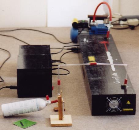
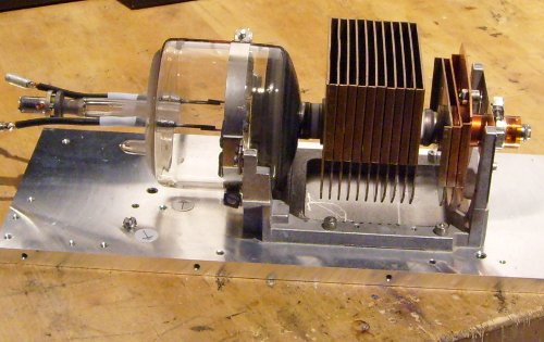
Picture 2 - Another total view of the laser, front side. As visible, I prefer for vacuum lines glas tubes connected by short pieces of vacuum hose. This design to my experience causes quite low outgassing rates. High voltage cables are spark plug cables from a car spare parts market, it stands up to 40 kV.
|
|
|
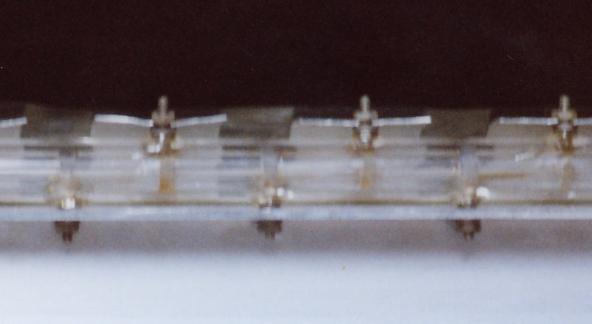
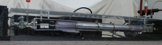
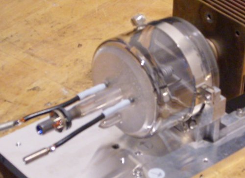
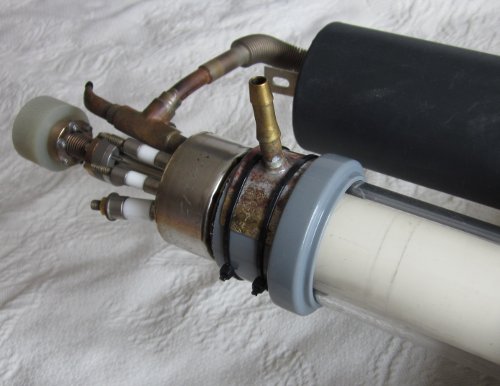
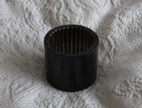
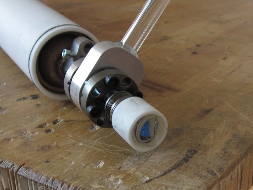
Picture 3 - Closeup view of the laser tube. The segmented
design is visible, in an outer tube of plexiglass there are short pieces of
pyrex tube with 3mm inner diameter. Between the pyrex tubes the electrodes
enter the tube alternating. Both transmission lines of the Blümlein are the top and bottom of a capacitor stack located behind the tube. The common line is between them (not visible) - so the Blümlein is folded. The upper line is slotted allowing a variable length of the discharge; the spark gap is connected to the bottom transmission line. |
|
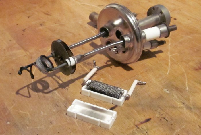
Picture 4 - Rear end of the laser tube with external
aluminum mirror. It is located on an insulating wooden rod and can be adjusted
by three screws outside the box - so high voltage cannot escape this way. The mirror has to be as close as possible to the glow discharge inside the tube. Due to this, the reflected laser pulse has a good chance to travel down the bore as long as the discharge is on (from this idea a quite simple method of pulse duration measurement can be derived). Also visible the quartz window and vacuum line of the tube, connected by flanges. This allows a more easy exchange if necessary. |
|
|
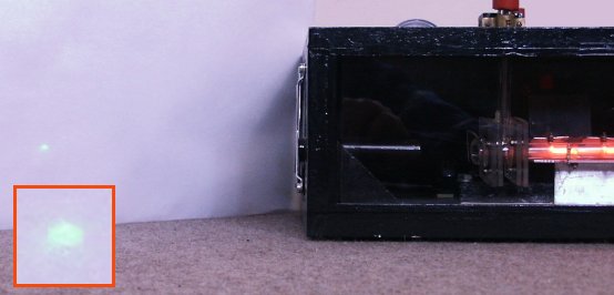
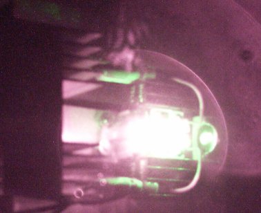
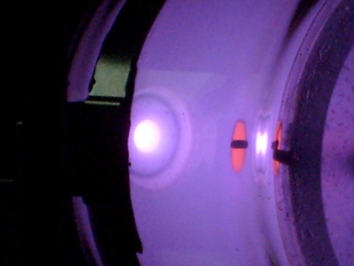
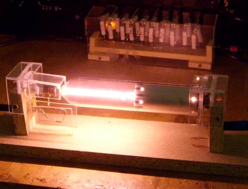
Picture 5 - Enhanced contrast. Laser action in
neon. It is not an easy task to photograph a nanosecond pulse on a white screen. The picture is the one hit out of 39 exposures (!). The laser spot is enlarged to give more detail, unfortunally it is too pale in this reproduction. Originally it should look like this. At the right end a tube segment with the salmon red neon glow discharge. short movie of neon laser pulse burst (MPG, 524 k) |
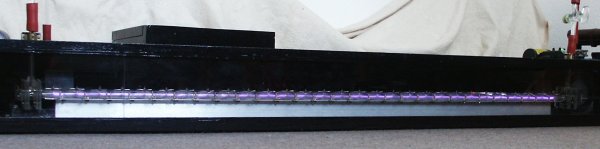
| Picture 6 - The violet glow discharge when running the tube with nitrogen as an UV laser. Entire tube shown. |
|
|
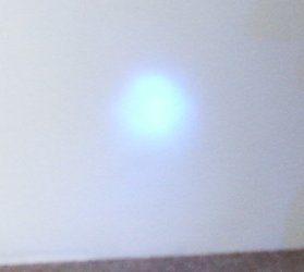
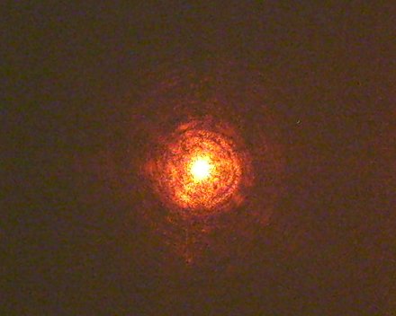
Picture 7 - Farfield spot (10m) of fluorescence of the UV
laser beam on white printer paper (the white toner in it shows a blue
fluorescence when exposed to UV). Long time exposure, several pulses superimposed. Note the nearly circular beam cross section which is uncommon for nitrogen lasers. |
| Technical data of the "Querflöte" laser | ||
| type | transverse excited pulsed gas laser driven by Blümlein generator, free-running air spark gap |
|
| length of transmission lines | 10+10 | cm |
| capacity of transmission lines | 10+6 | nF |
| charge resistors | 29x 1 | MOhm |
| operation voltage | 10 | kV |
| stored energy p. p. | 0.8 | J |
| electrode separation | 14 | mm |
| electrical field strength | 6700 | V/cm |
| pulse frequency (roughly adjustable) | 0-50 | Hz (erratic) |
| pulse duration | ca. 3 | nsec |
| length of discharge | 98 | cm |
| diameter of discharge | 3 | mm |
| discharge volume | 6.9 | cm3 |
| beam divergence | ca. 3.0 | mrad (measured) |
| possible pressure range | 0-120000 Pa | (-1 to 0.2 bar [c] |
| gas consumption | ca. 10 | l/h |
| Observed laser lines | |||
| nitrogen - | 35 Torr | 337 nm | 4-5 mW (mean [a]) |
| air - | 35 Torr | 337 nm | 1.5 mW (mean [a]) |
| neon - | 58 Torr | 540 nm | 0.6-1 mW (mean [a]) |
| neon - | 930 Pa (7 Torr) | 614 nm | (quite weak) |
| helium-nitrogen (?) - | 1333 Pa (10 Torr) N2 + 1 bar (?) He - | 428 nm ? | (only at one occasion, not reproduced until now. Beam went straight through an UV block filter used to kill the also present 337 nm UV from N2. So it cannot be just a fluorescence effect!) |
| Examined gases without laser action [b] | |||
| helium - | 0 - >13333 | Pa (flow through mode) | |
| argon - | 0 - >>13333 | Pa (flow through mode) | |
[a]
Measured by silicium-PIN-photodiode. I have no idea if it is
suitable for measurement of nanosecond pulse chains. So the real output power
could be higher.
[b]
In visible range of the spectrum 400 - 700 nm and near- IR and UV
which can easily be detected by means of simple indicators (overall 300 nm -
1.4 µm). Argon was of welding grade.
[c]
In helium, a stable glow discharge can be sustained up to atmoshere pressure or
higher, possibly even higher than I did - but the vacuum hose pops off the tube
at approx. 0.5 bar overpressure. :(
In 2004 I restarted the project for a "divided by two" tube - now it was a common longitudinal pumped laser. Nevertheless I kept the name of it, even if there remains not much of the original plan.
Janus II was planned more or less as a copy of the Erikson and Lidholt laser [2] which was used to check for laser action in various gases. The bore of it is much longer than for Janus I so a much higher operation voltage became a necessity. Hum, to be honest, I always dreamed to have a Marx generator - here was the reason to built one.
Pumping of longitudinal nanosecond lasers is done in a certain way. A network of two capacitors is coupled by a resistor and a spark gap. The storage capacitor can be replaced by a marx bank, the peaking capacitor is set coaxially direct onto the discharge bore to have the lowest possible inductive load. This basic principle already worked for Janus I. However, for the much longer bore of the Janus II laser I needed a voltage of 60kV - which meant a six-stage marx connected to my power supply.
|
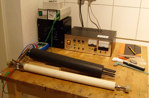
Picture 1+2 - The tube of Janus II, the marx generator, vacuum supply and HV power supply. The picture below shows the discharge tube in some more detail. Easy to see the silvery cylinder of the peaking capacitor (500pF / 100kV) inside the laser head. It is located coaxially on to bore, connected to the electrodes by metal pieces as short and thick as possible. The dielectric, a long piece of wrapped vinyl, is oversized by about 10 cm to prevent arcing over. Left of it centered the thin discharge bore. In the background the box of the Marx generator. Note the heavily insulated 60-kilovolts connection line. |
|
Diagram 1 - The charge transfer circuit schematic. Both capacitors are seperated by a low ohm resistor R (ca. 10 Ohm) and a spark gap SG. The storage capacitor C2 should have at least three times the value of the peaking capacitor C1 [3]. On principle, the combination of SG and C2 can be replaced by a n-stage Marx bank as is suggested by the red dots. In this case the series capacity of the marx bank capacitors should be at least three times C1. |
|
Janus II had some surprises for me when the initial tests began. Already the marx bank driven alone shoots some quite impressive 6 cm long sparks. Connected to the peaking capacitor it forms a system of coupled oscillators which can produce essential overvoltages [3] - I observed up to 10 cm sparks if the tube was plugged in but not pumped down (E/p measurements of laser action confirmed that the tube voltage is about 90kV in operation).
First experiments showed up the 337 nm UV nitrogen laser line and the 614 nm orange neon laserline also work in this longitudinal pumped laser device. Nevertheless, the Janus II design has some serious disadvantages:
(1) The extreme voltage is too unhandy for an amateur's laboratory. All corresponding modules need to have large volume - due to the neccesary insulation. Common spark plug cable isn't sufficiently insulated, too.
(2) The long thin bore is hard to drive in flow-through mode at very low pressures. Usually, laser action is present just for a few single pulses. Then the HV has to be switched off until the bore has "flushed". For neon (~200 Pa), this is quite pronounced.
Thus, I abandoned the Janus project the second time now.
|
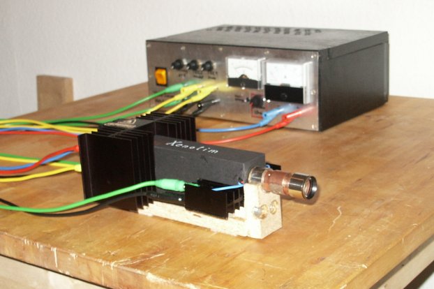
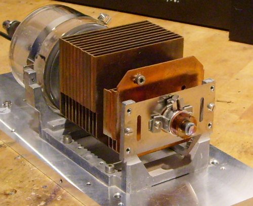
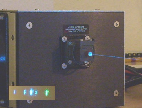
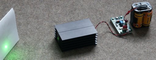
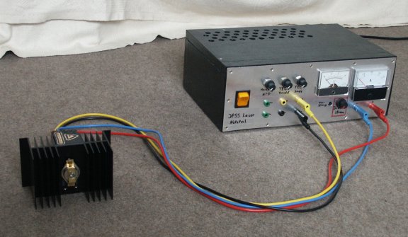
Picture 1 - Total view of the Xenotim laser - somewhat smaller than my other homebuilt stuff (see above)! In the background the power supply with diode current regulator and supply for the thermoelectric coolers (TECs). Lines are ordered by color. Red/blue diode feed, yellow/black for the TECs and green/green for a heater. |
|
|
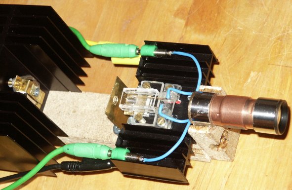
Picture 2 - Detail view of laser head interior, cover removed. At the left end the laser diode, a collimator lens is held in front of the output window by brass clamps. In the middle the focus lens (vertical brass plate) and the heat sink on which is mounted the DPM crystal with cooler and heater. At the right end the telescope which collimates the green output beam. As well the diode module as the crystal module can be removed from the base plate to be used for seperate experiments. (The collimated pump laser beam is a very good tool to manufacture optical pinholes from black cardboard... ;) |
I decided to have a 500 mW pump diode (808 nm) and a Casix hybrid crystal DPM 1101. From a fincancial point of view, it was an investment in the order of one of the better green laser pointers - I did it driven by the hope to get much more power out of it than from an ordinary pointer. The latter became true. :) All other are common electronic parts or scrapped optics.
Power Supply:
Core of the power supply is a lab power supply module from a local electronics shop. It allows to adjust voltage and current seperately, I decided for a max. 3A type to have room for later extentions. Voltage rough adjust is set to a value which allows the fine adjust values between 1.5 and 2.5 volts. This should be compatible to quite a number of laser diodes. The module is feeded by a standard 25W transformer.
Some experiments with a laser diode simulator (2 Si rectifier diodes and 0.2 Ohm resistor in series) showed up some problems. There were substantial voltage spikes when switching on and off - necessary to include some power on delay. Now the diode lines are enabled 1 sec. after power-on, at power-off they are disabled immediately. When not powered, the diode lines are kept shorted (ESD protection). At present, the real diode has 40 hours on it and some 30 on/off cycles and is still happy.
A second transformer in the power supply case feeds the TECs of diode and vanadate. I did it the easy way, a bridge rectifier feeds into constant voltage regulators of sufficient power. Adjust is done via power resistors.
An additional adjustable output is for a KTP heater.
Pump Diode:
The laser diode is a 500mW type L081T500m, manufacturer HTOE. My specimen has a wavelength of 806.7 nm at 25 deg C and puts out 500mW at a current of 570 mA (tells the distributor's test sheet). Its TO-3 case I mounted with a 4W TEC to a well overdimensioned heat sink of 1.1 K/W. Here also is room for extensions. The back of the heat sink contains a reverse protection diode and a RC filter ESD protection. The connections are mounted in a way a shunt can be plugged in as transportation safeguard.
Pump Optics:
The pump optics origin is the scrapped pickup of a dead CD writer. A CD is read/written at a wavelength of 785 nm so the AR coatings are still good for 808 nm. The short-focus (f = ~3.5mm) objective lens, glued to a small piece of brass now is the collimator lens of the pump diode and part of the diode module. Sadly the numerical aperture of the lens allows to collect only 85% of the very divergent diode output, but this is bundeled to a more or less parallel beam (at least for half a meter or so) of changing rectangular cross-section. The focus lens of the pump optic I put to the point where the cross-section is roughly a square.
The focus lens (f = ~8 mm) is glued to a seperate stiffened brass plate. By oversized bolt holes it can be adjusted horizontally, by a stack of washers and rubber "O" rings between brass and base plate it can be adjusted vertically.
DPM Crystal:
As mentioned above, the crystal is an optical contacted hybrid crystal DPM 1101 (not one of the glued DPM 0101's) of the manufacturer Casix. It combines 0.5mm Nd:YVO4; 2mm KTP; mirror 1: AR @ 808nm, HR @ 1064nm, HR @ 532nm; mirror 2: HR @ 1064nm, AR @ 532nm in one crystal module. The tiny little crystal has to be cooled if pumped that powerful - at least the vanadte part of it which has to absorb most of the pump power. I glued the vanadate end of the crystal to a brass cooler by use of epoxy mixed with silver powder (in liquid state I added silver until it reached a consistency of tooth paste). Of course the mirrored end facet of the vanadate must not be degraded by it, not an easy operation. The brass block is clamped onto a 4W TEC, and by my home-brewed silver epoxy there is a good thermal contact of the crystal (I checked this by glueing a dummy before).
The free-standig KTP end of the crystal is surrounded by a heater coil (NiCr, 0.3 Ohm) without touching it. It can be used to control KTP temperature; of course the control is somewhat restricted for the KTP is in direct contact to the cooled vanadate. See also picture 3 (below).
Telescope:
Purpose of the telescope is to reduce the divergence of the green output laser beam somewhat. For a hybrid crystal has short resonator length (2.5 mm) divergence isn't that well. Both lenses are from an old 24.5mm microscope eyepiece. They are uncoated so causing some reflection losses. The eyepiece tube I sawed in two and lengthened it by some copper plumbings so it became a 2:1 telescope. It can be adjusted with respect to the output beam by some oversized bolt holes and rubber "O" rings.
|
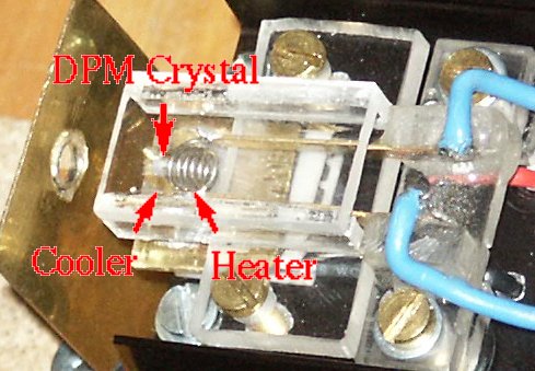
Picture 3 - Enlarged detail view of the mounted crystal. The DPM crystal itself is hard to see, it is easier to see the brass cooler the crystal's vanadate end is glued to by silver epoxy and the NiCr heater coil which surrounds the KTP end. Beyond the transparent plexiglass clamp the TEC is partially visible. |
|
|
Diagram 1 - The orientation of the DPM crystal *does* matter for the vanadate's absorption is polarization dependent. The DPM 1101 has glass splints on its sides so orientation can be displayed well. Shown the optimal orientation I found for my specimen, this way it absorbs roughly two times as much pump light as turned by 90 degress. To measure the pump optics need not to be in place, it is sufficient to watch out the weakening of the collimated pump beam of low power by the help of a solar cell or photo diode. |
Temperature management of diode and crystal is done manually. I performed a number of systematic measures to find out the diode temperature in dependence of current, TEC setting and environment temperature. Same I did for the vanadate cooler to find the optimal TEC setting to get maximal green output for a given pump power and environment temperature. So I have now a table which gives the optimal TEC (and heater!) settings for a number of temperatures and diode currents.
The influence of the KTP heater is highly nonlinear. Very often it is claimed a heater cannot be used for the tiny little hybrid crystals. To my experience, this is not true. At very low to medium pump power, by fine adjust of KTP heating the output can be increased by 5-10%.
Low Pump Power:
Here the temperature of the crystal doesn't increase enough by absorbed pump power to bring the KTP to optimal temperature. Cooling of vanadate not neccessary (actually it would decrease output), KTP heating increases output power.
Medium Pump Power:
The absorbed pump power is large enough to require vanadate cooling. However, the optical flux inside the resonator still is too low to heat the KTP enough, at least not against the vanadate cooling. Heating of KTP end (some cases a bit, some cases more) still can increase output power.
High Pump Power:
Pump power and flux inside the resonator now require massive vanadate cooling. But the losses now heat the KTP sufficient so no more heating is needed.
There can be speculation if the KTP heater does only a temperature fine control of the overall DPM crystal (not only the KTP end). I did some experiments concerning this by measuring the ratio of 532nm vs. 1064nm outputs. I had only filters of a relatively low quality so I couldn't measure the output directly but just the ratio of the various wavelengths. Even if the total (532 + 1064 nm) output power doesn't increase much, the ratio changes in favour of the green component which is an argument for an influence of the KTP temperature:
| no KTP heating | optimal KTP heating | |
| 532 nm | 0.5 mW | 0.6 mW |
| 1064 nm | 1.3 mW | 0.9 mW |
| 808 nm | 0.2 mW | 0.4 mW |
Easy to see that the power ratio (532:1064nm) changes from nearly 1:3 to 1:1.5 which is better. Measured by use of a monocrystalline (blue) Si solar cell, spectral response at the different wavelengths taken into account.
The green laser output power of the Xenotim laser with optimal settings (at least until now) for a number of diode currents is given below. Note that the table is valid only for an optimal position of the pump spot which is very close to the cooled side of the vanadate. At other positions of the pump spot (e.g., at the center of the front facet) the output maximum is lower (approx. 15 mW @ 400 mA) and cannot be increased further by an increase of pump power input. This clearly shows the influence of the low thermal conductibility of the vanadate which is close to that of glass.
The values below are in the order of magnitude to what Casix promises in the DPM 1101 datasheet, at least if the losses in the telescope are taken into account:
| diode current | net pump power | laser power @ 532 nm |
| 210 mA | 80 mW | (threshold) |
| 250 mA | 110 mW | ~1 mW |
| 300 mA | 160 mW | 3 mW |
| 400 mA | 250 mW | 13-15 mW |
| 500 mA | 385 mW | 22-24 mW |
| 570 mA | 425 mW | 30-33 mW |
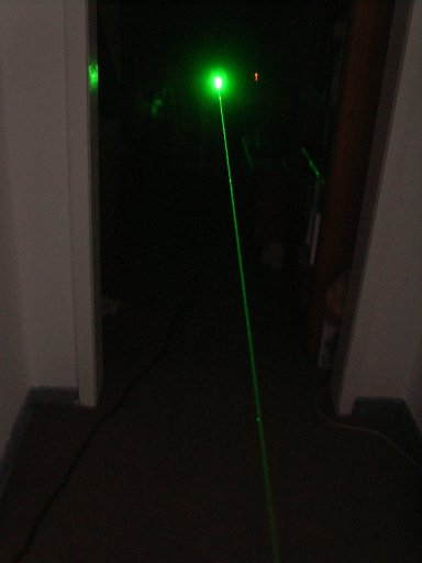
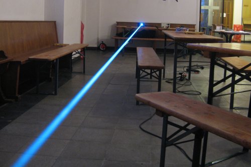
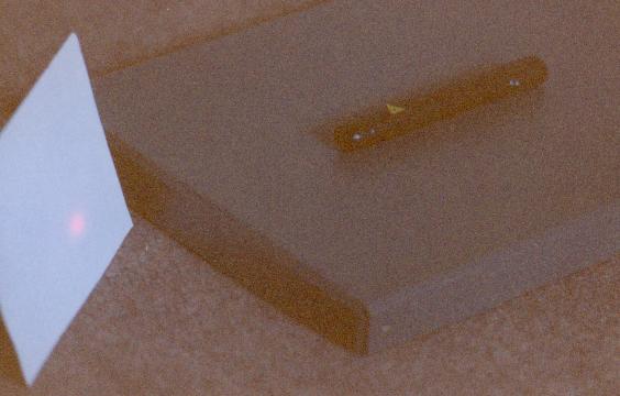
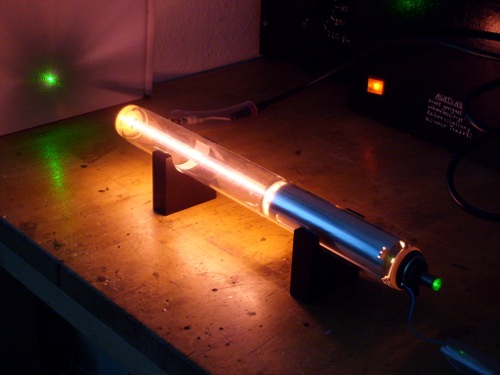
| Picture 4 - View of the beam in evening dim. Power level approx. 30 mW. Note that the photo was taken *without* the help of any artifical smoke or fog, it's just the scatter on natural dust particles present in air which makes the beam visible. |
|
|
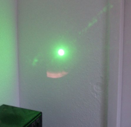
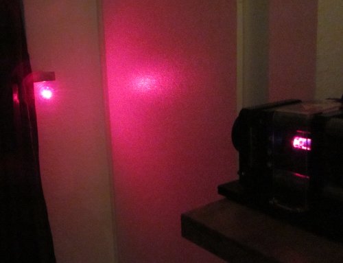
Picture 5 - Beam reflection at my living room wall, ca. 12 m distance of laser. The core beam is overexposed and appears white at the photo. Also visible at the photo only is the reddish arc below, here the camera has taken an image of the non-absorbed part of the pump laser beam. Invisible to the naked eye, it also can be seen on an IR indicator card. The irregular small green spots are reflections from the non-coated telescope lenses. |
| Picture 6 - What looks like a view to the "hot spot" of an arc welder is a photo of the scattered pump beam inside the opened laser head. The naked eye sees only the relatively weak scattered green laserlight (here visible at the fins of the crystal module heat sink). The totally overexposed white pump beam scatter is visually just a tiny little red spot at the crystal front facet - a very impressive demonstration how misleading the *visible* laser light from a pump diode can be! |
|
In the output beam there are substantial parts of invisible infrared laser radiation. Some of it is non-absorbed pump power, some of it infrared laser which leaked off the crystal (finally, even not a HR laser mirror is totally perfect). Both of them are in the order of magnitude of the desired green laser beam so they cannot be neglected. For a certain case, I took a number of detailed measures:
Measure at 500 mA diode current
diode temp 24.3 deg C (equals 806.1 nm), vanadate cooler temp 14 deg C, KTP heater "off"
environment temp 18.5 deg C
1064nm radiation detectable at far field ca. 1 diameter off-axis to 532nm beam center.
| wavelength | value | |
| electrical input power, diode: | - | ~900 mW |
| pump power, Diode: | 806 nm | 460 mW |
| net power input, crystal: | 806 nm | 390 mW |
| not absorbed pump power (divergent): | 806 nm | >15 mW |
| crystal output, infrared: | 1064 nm | 20 mW |
| crystal output, green: | 532 nm | 28 mW |
| not absorbed pump power, telescope output: | 806 nm | 13 mW |
| same, part in main beam (through pinhole): | 806 nm | 1.5 mW |
| telescope output, infrared: | 1064 nm | 17 mW |
| telescope output, green: | 532 nm | 24 mW |
|
Diagram 2 - The fact my pump diode is a bit short in wavelength and the cold winter weather in January 2005 made possible to measure the lower end of the vanadate absorption peak. Absorption coefficient here is displayed by laser output of the crystal. Input power is constant low ~160 mW (300 mA diode current), vanadate cooler and KTP heater both switched off. Wavelength varied by temperature control of the diode in the range of +7 deg C to +26 deg C. Note the local maximum at 804 nm which corresponds to a side absorption band inside the 808 nm main peak of vanadate. To be resumed in summer...! :) |
Conclusion:
It doesn't need a 1W or 2W pump diode which fries a DPM crystal close to death to get a simple-design respectable-power laser. The former too often was claimed at the hobbyist laser forums I saw. A bit temperature optimization does the same job at medium pump power keeping the crystal happy and long-living.
The Xenotim laser, despite of the bells and whistles added for TEC setting, is the most simple laser I ever built, one of the cheapest, surely it has the highest efficiency and is by far the easiest to transport. Once warmed up and tweaked for optimal power, I can let it run alone for hours if the environment temperature is at least roughly constant. It needs no consumables. And, it puts out laser radiation at a level not seen before.
Nevertheless I don't view the Xenotim laser as a true homebuilt laser. Sure, it is a robust tool for experimentation but its core is a bought hybrid crystal which is a complete little laser like a HeNe tube is. In the end I didn't much more than add a pump source and some temperature control.
|
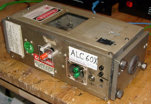
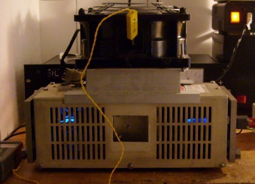
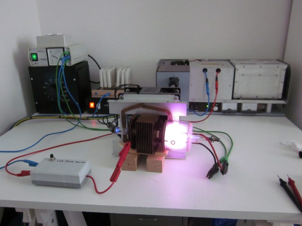
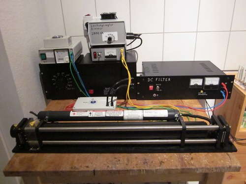
Picture 1 - Current state (Nov. 2010) of my ALC60 in operation. Left in the background the DC filter, right of it stacked (bottom to top): neon sign transformer for the starter box (grey in front), 115V transformer for the head's cooling fan, at the top the filament transformer. Below the table stands the electric room heater I use as a load resistor. All modules are described in detail below. |
|
Picture 2 - Board with test PSU for single pulse operation. The HF bridge is removed here for I put it into the DC filter. |
|
|
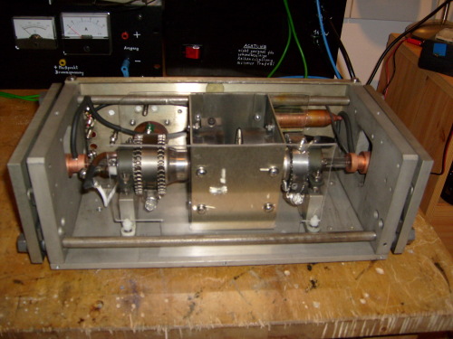
Picture 3 - Originally my filament transformer was the oven transformer of a defunct metal vapor laser project. Base is a 300W toroidal transformer; its secondary is simply left open & insulated. Fine regulation of filament current is done by a dimmer which was already in place for the oven of the MVL (see text). The fan hood for cooling was added after all else was finished. |
|
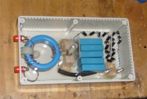
Picture 4 - View into the opened starter box. Visible are the series of ordinary caps and diodes which form the HV components. The big ferrite core is a remain from another project and now forms the ignition transformer. Primary is 2.5 turns, secondary 8 turns. The copper wire has to stand the full tube current in operation so choose a suitable strength. |
|
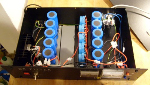
Picture 5 - View into my main PSU. Left end the bridge rectifier bolted to a heatsink. The big cylinders are the caps in parallel, close to center in between the chokes in series. The front cover has some meters attached. Rightmost partially covered by the front cover the HF bridge which connects the output jacks. All internal connections are made with 4mm2 wire. A 19" steel case holds everything in place - just for the case one of the big caps should ever have a really bad day... |
|
Picture 6 - The modified ALC60 head opened. Clearly visible the transparent "PCB dummies" which direct the cooling air strem as designed for the head. Note the white nylon screws at the tube sockets. The anode lead is hardly to see, I made it from spark plug cable to prevent any arcings to the back cover. |
|
Picture 7 - Back side of the modified ALC60 head. Red is the elevated terminal for the HV-insulated anode lead. It slips through the hole which served for the fan lines in former life. Green filament terminals rest on a piece of plastic which covers the big hole of the former main head plug. Black plugs are from the light sensor. I left its black box attached to the OC, maybe later it can do something useful. Silver - ground plug for the case. Lifesaver! Black rectangle atop is the hourmeter. I installed some custom 115V plug here which in operation is feeded from the fan cable (not well visible). |
|
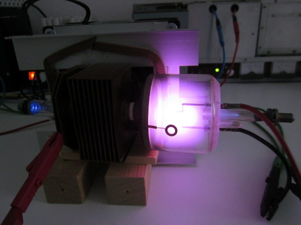
Picture 8 - The ALC60 head operation at 4A bore current. Due to the transparent PCB dummies, the glow in the glass stems of the tube can be watched via the air inlet openings. Fan is set atop the head by a spacer made of aluminum profiles and epoxy. Fan supply is by a separate 115V transformer (I have 230V line). Yellow wire belongs to a thermo sensor: I drilled a small hole in the fan case in such a way that the thermo sensor can be plugged down onto the BeO ceramic core. The display of the thermosensor is visible left of the head. The core temperature can be monitored this way, it is 55 deg C at 4A and 90 deg C at 7A. |
|
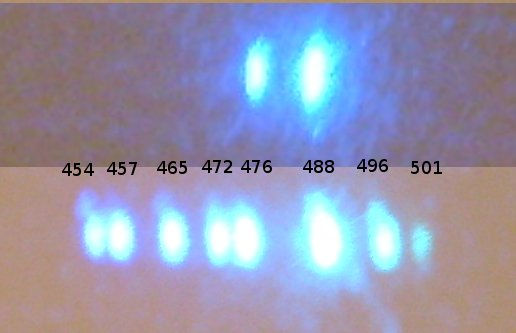
Picture 9 - Two (bad) photos of the laser lines at 4A (above) and 7A (bottom). A simple diffraction grid can be set up from a piece of unburnt CD-R; it can be used to show the laser lines. Sadly the beautiful colors aren't visible in the photos. Total power 5mW at 4A (80% of it at 488nm), approx 25mW at 7A. Values measured after the resonator has been tweaked for maximum power. |
|
|
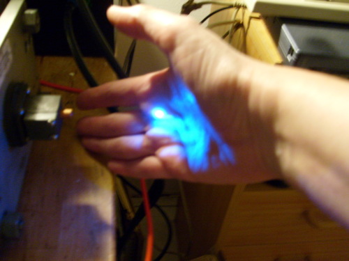
Picture 10 - Snapshot of the "first light" of my ALC60X. The blue reflection in my hand is quite overexposed. |
| Measured value | Preheat | R = 48 Ohm | R = 24 Ohm |
| Anode voltage | 0 | 98 Volt | 112 Volt |
| Anode current | 0 | 4 Ampere | 7 Ampere |
| Filament voltage | 3.00 Volt | 2.95 Volt | 2.90 Volt |
| Current in filament loop (AC+DC) | 25 Ampere | 29 Ampere | 31 Ampere |
| Laser power | 0 | 5 mW | 25 mW |
| Laser linies | - | 2 (488+476nm) | 7 (454-496nm) |
| Core temperature | - | 55 deg C | 90 deg C |
|
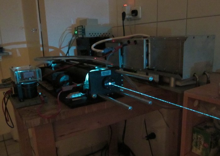
Picture 1 - Lasos LGR 7801 ML (due to lack of information I call it this way) at my lab desk surrounded by a bunch of meters of different sorts. Background shows the PSU modules I set up for my ALC60 (and which well can drive a Lasos head also). Just note the dimmer cannot be used here due to the lower filament power so I plugged the filament transformer into my variac. Contrary to the ALC head, a LGR7801 can be driven without cover. Inside the head there is a support structure which can be taken out. Put atop the tube, it supports the (unscrewed) fan from the head very well. This way cooling air flow is supplied same way as if the tube would still reside inside the head. As far as I know Lasos is the only manufacturer of glass argon tubes today. In the image, violet glow inside the glass belly is overexposed. Left picture border the blue-green laser spot on my solar cell power meter. Addendum: This time I managed to take a true color photo of the lasing lines. The inset at the bottom shows the 8 lines which I get at 4.4A. |
|
|
Picture 2 - Glass belly detail with glowing filament. I wondered some time about this tube's cathode heating. In the LGR 7801 data sheet (download at Lasos homepage) there is stated 2.25V at 18 amps. Slowly turning up current for preliminary testing resulted in a voltage way below 2 volts at 18A. But the filament already had the nice bright orange glow known from a peek through the ALC60's HR mirror. So what? I did a cardinal mistake here at first - if you compare filament glow colors, you must look through the HR mirror on BOTH lasers for the mirror filters the filament glow. On the ALC, of course we cannot see the filament directly... doing it correctly, at the same glow color of course the filament voltage was 2.25VRMS as stated in the data sheet. Just a higher power tube wants a little more filament amps. I measured 21A now. Postscriptum: meanwhile I managed to measure the cold resistance of the filament, it's roughly the same as for an ALC60, about 20 milliohms. As we can watch the cathode structure through the glass envelope, it's time for some calculations. The filament wire has square cross-section of about 1mm strength. The overall coil has 6.5 turns at about 8mm diameter. In comparison to the measured 20 milliohms this does a better fit to the specific resistance of tantalum (which is nearly three times that of tungsten). Guess this is due to the fact filaments of this kind are made from sintered tungsten powder. Thus they haven't the same effective cross section as a massive tungsten wire has. |
|
Picture 3 - View of the "hell's gate". Entering the BeO bore, the plasma really gains hell-like temperature. Even if the bore itself still is overexposed, the rest of the discharge colors are roughly right. Too sad I wasn't able to take a photo of a quite interesting phenomenon: by naked eye there can be seen a weak grey layer around the cathode. Using a small spectroscope, lines of neutral argon are identified easily in this layer. If the filament power is reduced in operation of the laser, the grey layer becomes thinner until it disappears at 2.0V. At this point, the violet plasma reaches the filament, and probably sputtering starts. (For the sake of science, I sacrified some of the tube's remaining lifetime to check for the disappearing layer). That's what's so cool on a LGR 7801: you can see all this fascinating stuff live in operation. |
|
During testing it, the tube ran with some respectable output. The low mileage of 2000h may be responsible for this. Using 48 Ohm load resistor, it draws 4.4 amps (@ 85 volts). Power done already was 17.5mW all lines (8 total, 514-457nm). That's more than my big old ALC does.
24 Ohms result in 8 amps at 95 volts, and for this the little monster shoots a 83mW beam out which already stings at the fingertip (and melts a tiny hole in a red plastic screw driver handle). In the beginning there also is a 9th line visible (454nm) which disappears after some time of operation (at least if the case is removed). 514 and 488nm line are of roughly equal strength, third in power is 457nm.
Lasos tube runs hotter than the ALC60. Core temp (without case) is 85 deg C at 4.4 amps, 152 deg C at 8 amps.
|
Picture 4 - Of this kind of tube there are few images in the web thus I post some more here. Images of a complete head are found in some forums (google for "LGK 7872"). Profile of the LGR 7801 ML. Don't know which subversion or if this name still is correct at all. The tube had no markings except the BeO warning. Also I'm not sure if they replaced the original 25mW tube in 1998 or put a hotter 40mW type in. Image shows the mirror protecting end covers removed. There is not much in common with the Siemens prototype I saw in 1985 (except the outer shape). If I remember right, mirror stems were shorter. Anode end was of glass, too, the filament was with an additional getter located off-center. The metal shield between glass belly and bore was not yet present. The Siemens tube was 488nm singleline and did only 2mW. |
|
|
Picture 5 - cathode end of the tube with high reflector. The originally covering aluminum tube was fitted by some silicon rubber blobs. Gently rocking it back and forth will release it from the glass tube. By some long tweezers the silicon rubber can be peeled off until the aluminum cover can be removed. Mirror adjust screws are visible. By some (very gently) pressing on the mirror mount I found the tube's output can tweaked still more to about 90mW at 8 amps. Glass belly in operation becomes too hot to touch. However, this seems to be normal since the head has no air inlet slits at the glass belly's location. The aluminum tube in operation better is put pack into place, for the hot glass tube is quite sensible to cold air caused temperature warping. This can cost up to 25% of total power output. I used a strip of the black foam stuff used to protect semiconductors plugged between glass and aluminum tube. Don't forget to close any of the silicon fill holes which aren't covered by stickers. This will keep cold air outside. |
| Picture 6 - anode end of the tube with output coupler. Anode copper tube is wrapped into some amber plastic to insulate it from the (grounded) socket. Concerning the HV igniter pulse, this caused no problems so far. |
|
Update: the Lasos tube is somewhat picky about temperature management. Putting it back into it's original case, I got thermal stress which caused a power drop of about 50%. Obviously this was caused by uncontrolled entry of cold air through openings at the cathode/ HR-end of the case. Sometimes I was able to "control" laser power by plugging some of the holes by my fingers.
Back plate and feedthroughs must be tightened sufficient to keep output power constant. If you've got power drop at your LGK 7801, LGK 7812, LGK 7872 head (or another one out of the Lasos LGK 78XX series),
check if the black foam stuff seals between front- and back plate and the case top are still in good condition.
Using the case lowered the core temperature by some degree, too. At 8A now the 9th line at 454nm stays on all the time.
NOTE: the following numbers are valid for my tube. Since Argon ion tubes are quite individualistic, the table has no general validity. Due to a calibration error in my power meter, values are corrected vs. an earlier version of the table.
| Measured value | Preheat | R = 48 Ohm | R = 24 Ohm |
| Anode voltage | 0 | 83 Volt | 95 Volt |
| Anode current | 0 | 4.4 Ampere | 8 Ampere |
| Filament voltage | 2.25 Volt | 2.25 Volt | 2.25 Volt |
| Current in filament loop (AC+DC) | 21 Ampere | 21.5 Ampere | 22 Ampere |
| Laser power | 0 | 17 mW | 83 mW |
| Laser linies | - | 8 (514-457nm) | 9 (514-454nm) |
| Core temperature | - | 83 deg C | 142 deg C |
|
Picture 7 - My new playground in the new flat. In the back, left side Variac and filament transformer, right side the big SMPS from an ALC909. One can use the latter for smaller tubes too but must put a 3 Ohm resistor into the anode lead. Otherwise the current peak at tube ignition would trigger the overcurrent protection circuit of the SMPS. Left in the front of the tube is a box with the igniter PCB from a more recent LGK 7812 head. The old tube lases here at about 3A, 78 volts. |
|
|
Picture 8 - Detail of the tube. As usual for my "naked" tubes, it lies on its side in the sucking channel of a Tarzan fan from my ALC60. Clearly visible the reflection of the blue anode glow. The old Siemes style tubes had a smaller glass belly at the anode end, too. The copper heat sink has a slightly different shape than for newer tubes. The anode itself is smaller and has only two copper fins. Due to the overexposed discharge hard to see: the transverse cathode filament heated by 12.5A of AC. The correct heating voltage is handwritten on the tube label: 2.07 volts. Seems it was measured for each tube individually at that time. |
| Picture 9 - Once again the vintage tube, lasing towards the wall. Interestingly the old Lady has multiline optics. |

|
|
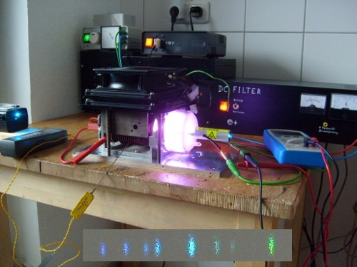
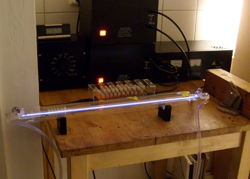
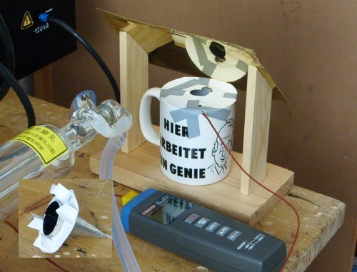
Picture 1 - The CO2 laser tube in its current shape (as of end January, 2011). In the back the HV supply; two neon sign transformers in parallel are controlled by a variac. They feed into a double cascade which generates a voltage of about 20kV. Water cooling is performed by a small pond pump in a bucket which pumps distilled water at about 10l/min closed-loop (bucket is located under the table, not visible here). The laser generates about 11 Watts at the photo, note the red-hot spot at the ceramic beam stopper. The tube is a standard 40W type of manufacturer Coletech (Anhui province/PR China), nevertheless for amateur experiments a few watts are sufficient. It's also less dangerous. |
|
End of 2010 I peeked around on Ebay and found the real cheap offers for sealed CO2 laser tubes. As the german saying is, "my fingers started to itch". Usage of such tubes of chinese production in cheap engraving and cutting machines for the mass market made prices coming down, similar as it had been in the past for laser diodes. Thus I ordered a tube to see what I get and how far I can do experiments with it. I was quite interested to measure power over a long storage period.
|
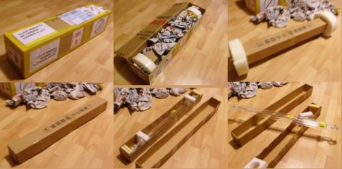
Picture 2 - Coletech webshop offers immediate replacement service should a tube break on shipping. However, should this be the case it is best to document the unpacking process by some photos. My tube was ok so I didn't need the photos. Just see a patchwork of them here for entertainment purposes. See lots of chinese newspapers. The tube box is held by two large plastic foam spacers inside the transport box. Inside the tube itself is fixed by additional styrene spacer and foam stuff (and lots of adhesive tape). Shipping was done within 3 days via air freight. Guess the fast shipping time left less chances to break the tube by accident. |
|
The tube is a piece of art from the hands of a glass blower (see details below). Except of the common laser warn signs there were no markings on it. I took some effort (and help of Leo.org) to approximately translate the writing on the cardboard box as "Technical glass ware - Caution! - Handle with care". Specs are available on the manufacturer's website only: ignition at 22kV, operation at 18mA @ 15kV, output 40W TEM00 @ 10600nm, beam diameter 1.95mm.
First test showed easy ignition, a stable discharge can be sustained already at 2.5mA. Usually I run the tube at 5mA (this is the limit of my cascade), corresponds to 27.5% of the nominal current. Accordingly I measure 11W output power which also is 27.5% of the nominal power (note on CO2 lasers the power depends linear on the bore current). I quickly found out this power is more than enough for simple experiments.
|
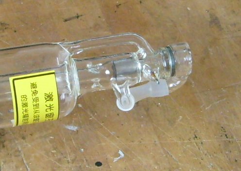
Picture 3 - Cathode end of the tube with flat output coupler. The latter here is made of germanium with a glass cooling envelope. Cooling water is in contact with the Ge surface, contrary to zinc selenide OCs which have a closed metal envelope. ZnSe must not come in contact to water for mild acids will etch it (releasing poisoneous gases). Ge is stable against mild and medium acids (and non-poisoneous). Usually cathodes of sealed CO2 tubes are made of sheet nickel which catalyzes regeneration of decayed laser gas. Cathode is of larger size than the anode and located at the OC end of the tube. |
|
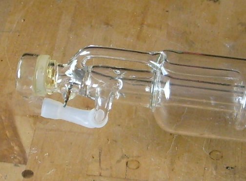
|
Picture 4 - Anode end of the tube. The high reflector is made of glass with a gold layer on it. It is marked with the signs "3>" which I interpret as a radius of curvature of 3 meters. Both mirrors are sealed to the tube with very clear epoxy. This looks much much better than pictures of other chinese laser tubes on older websites which have a smeared whitish-yellow zone of epoxy "snot" here. So the quality of the tubes obviously has raised a lot. |
|
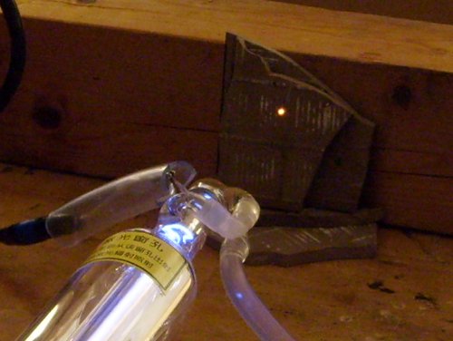
Picture 5 - Tube in operation. Inevitably the beam of such a laser must be catched by a sufficient fire-proof beam stopper. At about 10W, after a few seconds of operation a red-hot spot appears on the target. Carelessness can start a fire here very easy! I use ceramic bathroom tiles as a beam stopper. The large bar behind serves as second line of defense - ceramics tend to sudden cracks under the high thermal stresses. Note the stack of ceramic fragments in the beginning of my experiments was ONE tile. Needless to say, shiny metal parts are a big no-no in the beam path. Also, the tube must never be used without any eye protection. Infrared beam cannot enter the eye but it can (and will) burn your cornea irreparably. Even the poorest amateur scientist should not save the 5 euros for dust protection glasses from the local homeworker's store as an absolute minimum protection. It has at least a plastic sheet which probably will not stand a full beam hit, but at least it can protect you from shattered infrared radiation. The latter isn't to neglect. It can be detected by skin as heat if you put your hand BESIDES the beam stopper (NEVER put your hand into the beam path!). It feels like the beam stopper is hot entirely even if it isn't and its outer rim is on ambient temperature. Skin can detect small amounts of 10um radiation quite well. Large amounts will cook the temperature sensitive cells faster than they detect it. It is told you notice by the strange smell something has seriously gone wrong... |
|
|
Picture 6 - My "mug calorimeter". A polished sheet of brass reflects the beam downwards into a mug holding a defined volume of water. The beam doesn't enter the water directly but is absorbed by multiple reflections inside a cone made from thin aluminum sheet. This way the multiple reflections and absorptions let nearly no radiation be reflected back upwards. The cone has a thin layer of plastic paint on the inside. Any colour does, it hasn't necessarily to be black, since all plastic stuff absorbs 10um radiation quite good. A picture of the cone itself can be seen on the inset at lower left. A cardboard iris and some adhesive tape press the hollow cone into the water (else it would swim uncontrolled at the surface). A thermocouple measures water temperature. By the formula: "1 calorie equals 1 gram water temperature raise by 1 deg C" you get the input energy in calories from the temperature raise. Convert to Joule, and division by the exposure time in seconds results in mean power in Watts. The ceramic mug does a quite good insulation job as long as the temperature raise isn't too much (about 10 deg C). I use a water volume of 200ml and an exposure time of 10min (600sec) for most measurements. |
|
|
Diagram 1 - Development of power of the CO2 laser tube during last months. A slow decay of the output can be observed from the 3rd month on. Value is still within the warranty of the manufacturer (80% after 3 months of storage). Horizontal axis number of months, vertically the measured output power for 5mA discharge current in watts. During each campaign of 5-6 single measurements the tube seemed to recover a bit. Color of the discharge plasma changed from a whitish-purple to a more reddish tint. The red "C"s in the graph show the dates where I did two-hour "cleaning runs" which obviously improved the output of the laser. Latter observation seems to coincide with a property of old soft sealed HeNes: frequent powering-up cleans the gas at least partially and helps to prolong remaining lifetime of the tube. |
|
|
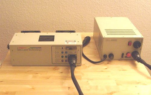
Picture 1 - That nice a 20 year old laser can look! This is my restored "vintage" ILT model 5490 ACM, multiline, multimode, current regulated, and it still does the 100mW at 10A which were printed in old brochures. At Imax it's still about 120mW (number extrapolated, I do not ram the control to the upper limit without any need). Emission in idle mode at 6A at the 5 lines 515, 496, 488, 476 and 457nm (overall 20mW). At 7.5A also 502nm kicks in as 6th line. PSU is a model 5400C which has been adapted for the European market. It runs from 230V single-phase. Inside it seems to be untouched since long years - contrary to the head. |
|
|
Picture 2 - Back side of the running ILT 5490. Scattered laser light illuminates the two teflon blocks which cover the brewsters and the mirrors, seen through the running fans. Modern variant of the 5490 has metal bellows here. ILT itself long time ago ceased to make lasers, but some companies (partially with the original ILT production staff) sell total rebuild lasers of ILT, with new tubes and better spec than original. Such a new 5490 doing 200mW will cost you about $5000. |
|
|
Picture 3 - The upgraded light sensor. Insiders easily will recognize the "copper nose" of an ALC60. Meanwhile I glued a TNC plug with cap onto it to come closer to the original view of the ILT light sensor. However, the original part was all in one which clearly is impossible with a transplant from my ALC. Thus I used small screws to fix the sensor on the replacement resonator cover. Photo shows the laser running idle at 6A at about 19mW. The beam scatters only at the natural dust particles in the air. Small inset at lower left edge shows the 5 lines lasing at 6A. |
|
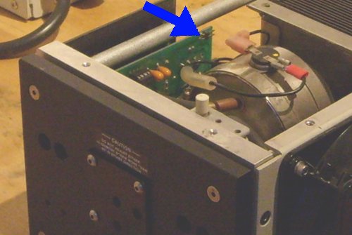
|
Picture 4 - Cathode end of the open laser head. Blue arrow points to the pins on the PCB where a light sensor can be plugged. Upper pin has a small "+" mark on the PCB which expects the positive lead of a small solar cell (like the one found beside the beam splitter in the light sensor case). I tested with a photo diode and a solar cell what will happen before I actually did the upgrade. I didn't want to see the regulator logic do quite strange things suddenly. ;) But everything kept safe when the solar cell was on, regardless of any light illuminating it. Opamp went into saturation at 13.5 volts at the output jacks. Calibration is done by comparision with an external laser power meter. Bottom of the photo also shows the second replacement resonator cover. Contrary to the original, it has a small circular window at the center (not visible: a small tilted piece of a microscope slide is glued in). This window lets the waste beam exit, but its main purpose is to check for cathode glow during startup. |
|
| Measured value | Preheat | Idle | |||||
| Anode current | 0 | 6 Ampere | 7 Ampere | 8 Ampere | 9 Ampere | 10 Ampere | 10.25 Ampere |
| Anode voltage | 0 | 102.2 Volt | 103.9 Volt | 105.6 Volt | 107.5 Volt | 109.3 Volt | 110.0 Volt |
| Filament voltage | 2.70 Volt | 2.65 Volt | 2.64 Volt | 2.64 Volt | 2.63 Volt | 2.63 Volt | 2.64 Volt |
| Laser power | 0 | 18.5 mW | 32.1 mW | 50.0 mW | 71.9 mW | 95.5 mW | 100.0 mW |
| Laser linies | - | 5 (514, 496, 488, 476, 457nm) | 5 (514, 496, 488, 476, 457nm) | 6 (514-476, 457nm) | 6 (514-476, 457nm) | 6 (514-476, 457nm) | 6 (514-476, 457nm) |
|
Picture 5 - I took the ILT 5490 to the laserfreak meeting 2011 in Essen city (Germany) where this nice old "gas lantern" triggered some nostalgic feelings in some of the attendees. Picture reproduced with kind permission of decix of the laserfreak.net forum. |
|
|
Picture 1 - Coherent Innova 60 tube during anti-sag treatment. Tube lies upside down, and the sagged filament is kept on dull red glow to make it soft at about 700 deg C. Hope is, this treatment will make the filament sag back. I needed about two days of try and error to find out the right current (9.5A). Treatment overall wasn't that successful, maybe 80% of the bore is free now while I started at maybe 66%. Somewhen during the treatment something very different happened: the tube suddely started to do a "singing" sound, and after it finished the voltage at a certain filament current was about 10% higher than before! I guess here some shortened loop of the sagged filament has opened due to the treatment. Photo also shows the two slightly smaller terminals at the cathode bell (without any cables attached). In the back besides the variac and filament transformer there is my DPSS laser supply. I used it as a constant current source for the measurement of the filament resistance. (At 1A, due to Ohm's law it holds Volts = Ohms. Pass 1A through the filament and read volts on a DMM.) |
|
About the strange additional terminals on the cathode bell even Aunt Google cold not tell me any little detail. Finally I asked Steve Roberts (yes, THE Steve Roberts) who told me the following facts:
|
Picture 2 - As I found out during "anti sag", the tube ceramics is slightly transparent. Thus I invested in a transparent cooling jacket. A 50mm plexiglass tube is plugged with both ends into grey vinyl tubing from the local homeworkers store. Cheapest is to buy one DN50 connector and cut it in half. Rubber adaptors for 1 1/2" tubing are available to close the ends of the vinyl, I had to cut them shorter to fit into the short vinyl pieces. Water hose plugs of brass soldered I to rounded brass sheet and glued that with some silicone sealant to the vinyl tube (and don't forget to drill the necessary holes to let the water in!!!). Some cable straps stabilize the connection. |
|
Magnet
It's not widely known that argon lasers can be operated also with permanent magnets. A publication describes the alternating axial field in a longitudinal stack of ring magnets [4]. The equation results in the interesting fact, that rings of equal diameter and length, longitudinally separated also by one diameter, will produce a magnetic field on the axis which has 1/10 of the flux density of the ring material. The direction of the axis field alternates from same direction as in ring material in the gap between the rings and opposite direction inside the rings itself. In the cited paper are reported quite good results for a number of the common argon lasers.
|
Picture 3 - I made magnet rings. From 288 small NdFeB supermagnets I made 4 big magnet rings. Of course, the small magnet bars are quite strong and don't go easily in same polarity so close together. First I made a outer shell of strong lacquered cardboard. Inside I glued every second column in place first. After everything was dry, I forced more columns into the gaps. The strong magnetic separation force presses them outwards against the cardboard shell. Such magnetic rings are quite strong, they pull small iron parts already if 30cm away. Be careful with such a beast! |
| Picture 4 - Cooling jacket and three magnet rings on the tube. First I made four rings but the 4th was partly over the cathode. I was not able to ignite any discharge, even with strongest setting of my igniter box. Don't know if that is from the 4th ring or a possible high gas pressure in the tube - I simply don't know. So the experiment goes on... |
|
A postscriptum: I measured again breakdown voltage and found it has increased from 5kV to more than 11kV now. Obviously something releases gas in the tube. Meanwhile any attempt to ignite it doesn't result in any reaction.
I decided to give my new ALC 909 SMPS and its igniter box a last try. If that doesn't work, I declare the tube as dead. Maybe it can be used for some future refill experiments, I don't know yet.
|
Picture 5 - A dead tube can be cut open. The totally deformed filament clarifies now why my anti sag treatment wasn't that successful. I tried to fix it but the at first attempt to bend it the whole thing broke apart. Looks like I have to care about a homebrewed cathode now. I got some tungsten wire, and a simple experimental vacuum glow of it demonstrated how brittle it became by this treatment. It isn't possible to bend it any longer indeed. The white box at the photo is the mysterious getter which was located at the bottom of the cathode bell. It housed a grey folded metal ribbon. |
Meanwhile I moved the DN50 flanges from the SP2017 to the Innova tube. I don't need two dead tubes for experiments, and for the Innova I already have a water jacket and magnets.
Stay tuned!
|
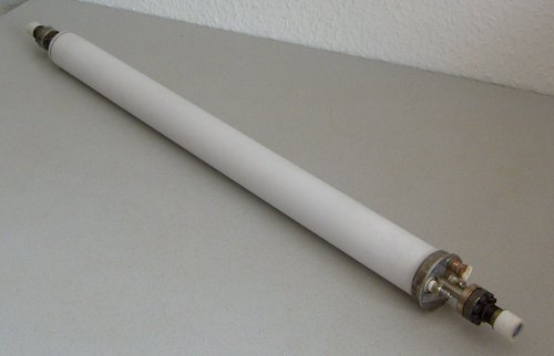
Picture 1 - This is a naked Spectra Physics argon tube. This way it looks if it is removed from its can-style resonator structure. Length about 70cm. Overall design with internal mirrors is quite compact. A special gift for any amateur is the fact that they use flanges on the tube ends! |
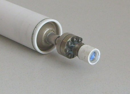  Pictures 2+3 - Anode end before and after disassembly. Between the flange is a copper sealing ring located. The broken mirror illustrates how the air leaked into the tube. I still wonder which force was strong enough to crack such a massive block of glass? |
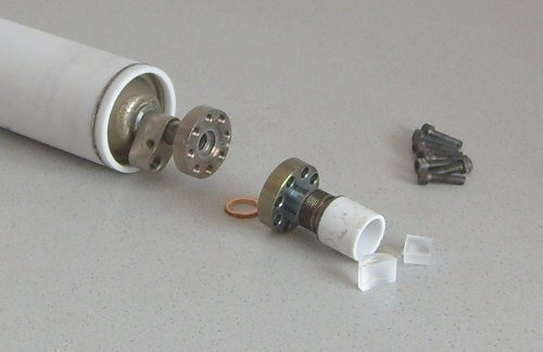
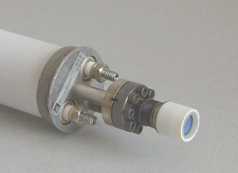 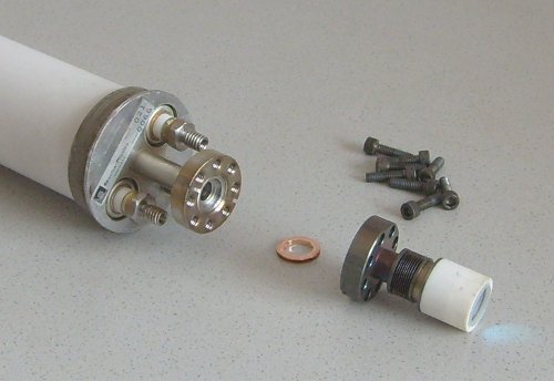 Picture 4+5 - Cathode end of the tube, with same type of copper sealing ring between the flange. Cathode-end mirror still is intact. Well visible are the two threaded filament terminals. The small label says "Spectra Physics Model No. 021" and shows the four-digit serial number. |
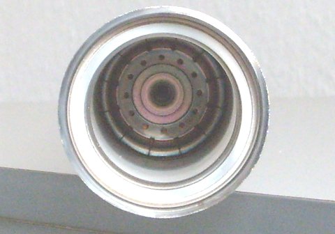  Picture 6+7 - The outer edge of the cathode-end bell is welded. Using a file tool it can be opened carefully (please take special care if you're subject of an allergy, the metal dust is nickel!). After that is done, the complete cathode assembly can be taken out. A view into the tube core shows the first of the massive copper discs which carry the tungsten inlays. The peripheral holes serve for backwards flow of the gas which was "pumped" down to the cathode by cataphoresis. Cathode assembly shows the filament and the broken weld spot. The tungsten coil still has a silvery surface which tells us the air didn't leak in during operation of the tube. It also tells there wasn't much sputtering of the cathode during its life. Since the broken weld cannot be repaired by amateur means, all this doesn't help much here. |
Modification for Pulsed Operation
A pulsed argon laser tube needs no magnet and no heated cathode thus it is much easier for an amateur to build one. Nevertheless, one needs high vacuum equipment and of course a HV supply. Both I already have from my homebuilt lasers. :)
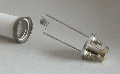
I removed the cathode coil (weld spots are really brittle so that's no problem) and replaced it by some length of aluminum tubing, similar to a HeNe laser. At the mirror ends there are some aluminum adaptors for T-connector tubes added, see below.
  Picture 8+9 - Here we have the cold aluminum tube cathode, similar as it looks like on a HeNe laser. Right photo shows the repaired anode-sided mirror. The aluminum T adaptors were made by nr_lightning from german laserfreak forum (thanks again!). The whole cathode end of the tube now has a DN50 lab flange, its seal can be seen below it (left photo). This way I'm free to try for a number of different cathode types. |
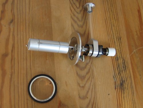
 Picture 10 - It's vac test time! Fortunately everything went well, the tube didn't leak after I pumped it down (and the initial outgassing ceased). Photo shows my rotary vane pump in action. None of the glued parts or flanges failed. |
Gave up at this point when the Innova 60 tube died, too. Two dead tubes are too much. For the I60 I already have magnets so the decision was easy. Rest of the SP2017 went as parts into several other projects. End of story.
|
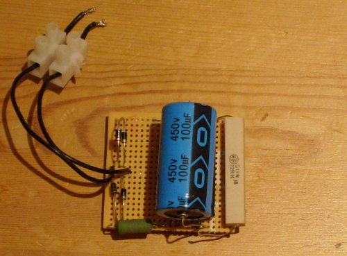
Picture 1 - Last trace of my early 1980ies dye laser project
is this drawing. Still it has a smell of the "dye cell replaces ruby"
philosophy. It was built as drawn, of course it didn't work. Even later modifications made no success so I gave up in 1985. |
|
|
Picture 2 - Finally my old Siemens HeNe tube died after nearly 20 years. So I had to get some replacement which was a Melles-Griot 05LHP122 I found at a local tube dealer. The tube is NOS (new old storage) but the dealer couldn't tell me how long it lay on the shelf. It still does about 2mW as far as my solar cell power meter tells me. If watching the dicharge by a spectroscope, both yellow spectral lines doesn't have same brightness anymore. So maybe it lost some amount of helium over the years. Update: it's not He loss, I've got a second tube from same source which has same appearance of yellow spectral lines but does 3.0mW. Who knows... |
| Picture 3 - Farfield spot (4 m) of the HeNe beam. Despite of some circular rings, isn't it a nice TEM00 beam? |
|
| Picture 4 - A red diode laser pointer, first generation (670 nm wavelength). For a time in my life it was the only functional laser I owned. I still use it to adjust the mirror of the Querflöte and Janus II lasers. |
|
|
Picture 5 - Once again the laser pointer with its red spot. Due to the exposure time the spot appears larger than normal. |
|
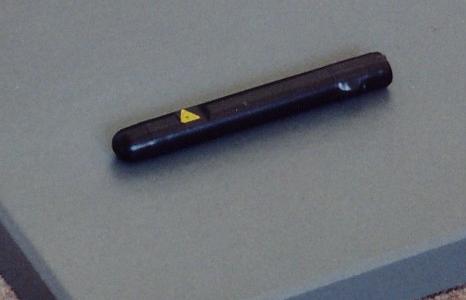
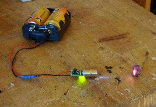
Picture 6 - A Nd:YVO4 micro laser module which I got as a present from a professional laser engineer (thanks, Peter!). I just added the heat sink and the battery pack. A nice laser for travel, it is small and powerful. Depending on temperature, it puts out 5-10 mW at 532 nm. |
|
|
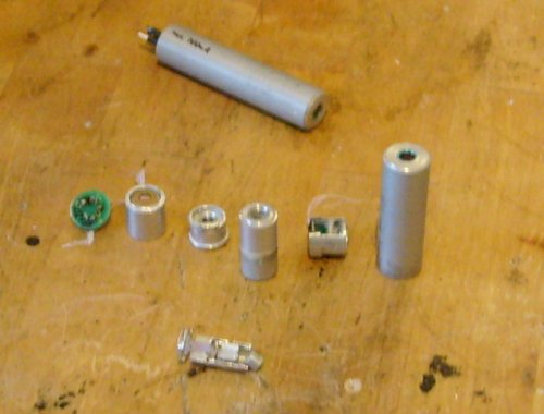
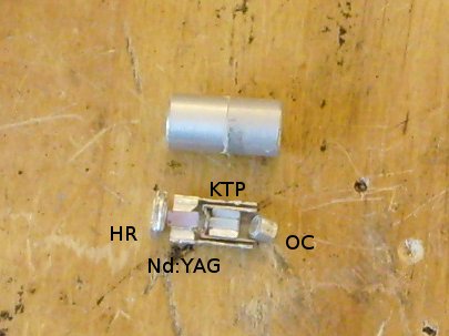
Picture 7 - Same source as above I got a handful of "dead" Nd:YAG modules. Some still did some green laser but of the rest I ripped apart one after the other to see what's inside. In the back is one of the modules as I got them. Mid row shows the main components inside, l.t.r.: adapter PCB, pump diode, pump optics; one step before the mid row the crystal module; right end lies the collimator/ beam splitter/ photo diode assembly besides the outer module tube (now empty). Forgreound shows a cut of a crystal module. I opened up one of the pump diode cans, inside was the largest laser diode chip I ever saw live: 3x1mm. Use a tubular cutter tool to disassemble modules of this kind. |
|
Picture 8 - Surprise was: the small Nd:YAGs are fully discrete internal! I ruined about two of them totally until I found out what's where. Top lies a crystal module, bottom I put all the (cut in halves) parts in the right places to show how it looks inside. The outermost tubes are removed. We see two external mirrors, one high reflector (HR, R=~20mm), one output coupler (OC, flat), a massive Nd doped YAG crystal (3mm diameter, 6mm length). KTP size is 2x2x7mm. All parts were glued into their respective aluminum tubes by some white epoxy stuff. For cooling purposes the HR end of the HR/Nd:YAG tube was quite massive. KTP and OC were glued into the smaller tube, KTP was held in place by a V-shaped Al-block. The crystal modules have a quite high quality, some of them start to lase if hold them into an unfocused (just collimated) pump beam! Meanwhile I salvage the crystals and mirrors only from crystal modules which didn't pass this test and keep all the others. |
|
|
Picture 9 - The pump diode of the Xenotim project is an impressing laser in its own right. The output of 500 mW at 807 nm is sufficient to show unsuspecting spectators exciting burning of any black stuff in its way... :) |
|
Picture 10 - When the first violet laser modules became cheap enough, I couldn't withstand any more. This GaN module emits a power of 7mW in violet. The web has enough bad photos which don't show the violet color so I put a natural ruby crystal in front of the laser. The violet beam excites a strong red fluorescence in the ruby. I wonder if one day a ruby laser of this kind will be built...? |
|
|
Picture 11 - Also a present of my love - it's simply crazy if your consort supports your hobby. A green HeNe of the Siemes / Carl Zeiss Jena / Lasos series. The tube, a LGR 7774, was built in 1996 at Carl Zeiss Jena. It's old and high mileage (has brown deposits in the bore) but still does 0.6mW. Picture shows it hooked to my lab HV supply (but I also have the original PSU for it). Runs at 2000V, 6.5mA but normally I tweak it to 5.5-6mA to save some lifetime. Due to the low gain of the 543nm line the beam has extraordinary good coherence properties. Speckle grains of a beam reflection of this laser are best visible of all my lasers. |
|
Picture 12 - A former dematology laser is this krypton-filled ALC 909D. It's my only water-cooled ion laser. Sadly my Pi-filter PSU is slightly overload when driving this 80cm beast so I'm only a bit above threshold of the 647nm line at 13A. Anode voltage is 240V, magnet current setting of 2.5A makes the brightest beam. Filament runs at 25A / 3.2V AC. Water supply is about 5 liters/min. Hoses are below the table. Since I do my experiments in a former kitchen, tap water isn't that far away. I also made a try with the pond pump in its bucket, but a 10 liter fill of water got too hot after only one minute of operation of the laser. |
|
|
Picture 13 - Again the ALC 909D with the beam spot of the red krypton line. At 13A the bore current is only about 1A above lasing threshold. Power is just a poor 20mW. But due to the low gain at this current the beam has very good coherence properties, similar as a green HeNe. Strong Speckle grains can be observed. More detail about this laser I posted in a thread in Laserfreak forum (in german only, sorry). |
|
Picture 14 - I wanted just a SMPS for my nice krypton tube above, but as things go... now I've got a complete ALC 909 Z which is the slightly shorter argon sister of the 909 D tube. In the photo, it is running at 15A. Don't know how much it outputs exactly for my solar cell power meter starts to saturate at about 400mW. Certainly this is more than 600mW. Even here, the spot is targeted for a black heat sink and the reflection still is able to illuminate the room. P.S.: Meanwhile I found out (using a homebuilt TEC-based power meter, calibration was done on the german laserfreak meeting 2011) the laser does about 1W at 15A. |
|
|
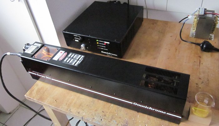
Picture 15 - As of December, 2011 I got this Omnichrome 3056 helium cadmium (HeCd) laser. It is old but has a replacement tube with low hours on it. As many Omnichromes, it suffers from helium overpressure from long years sitting on the shelf. But fortunately it still lases at reduced power for a tweaked setting. When it runs more hours consuming more He this will normalize over time. The 3056 is a tube from the Omnichrome 56X series which lases in the UV at 325nm. The beam becomes visible by fluorescence in some diluted rhodamine 6G dye solution. Current power is about 1mW. I got a PSU with the head for free which turned out to be still operational except for a dead filament regulator. Originally this thing was a Omnichrome 100 which had been reworked at some time by Melles Griot. It is not quite clear if MG changed it to 100B during the rework. Internally it has not the two 10k HV ballast resistors in parallel as a 100 has but a single 2.5k HV ballast. Even Sam G., who helped at the resurrection of this laser couldn't explain it. However, even if the previous owner had head and PS from different sources (and never ran them), both now run very happy together now. Also about this laser I posted a thread in Laserfreak forum (in german only, sorry). |
|
Picture 16 - The year 2012 brought me two Omni/MG 643s, here side by side. The first one was the grey Omnichrome 643-YB, which does quite bright krypton 568nm yellow and blue argon lines. It's old but has still low hours on it. The black guy is a newer Melles Griot 643-RYB which I bought from kilovolt (laserfreak.net forum, also on mosfetkillers.com). Both look IDENTIC inside with the only exception is the light sensor. However, the MG 643 has just a big black can around a light sensor looking quite similar to the Omni's. |
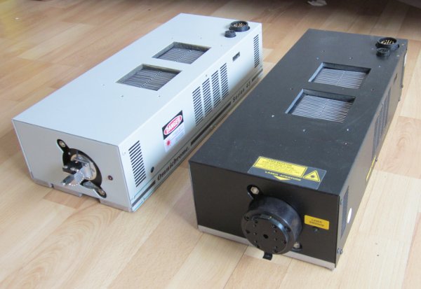
|
|
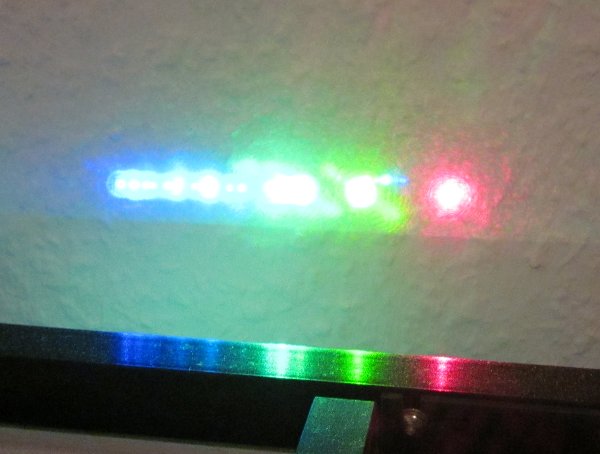
Picture 17 - The MG 643 RYB is a really funny thing to play with external mirrors. Here I get also the green Kr lines with the SP-2017 argon OC added. Got up to 15 lines oscillating simultaneously from argon and krypton (10 blue, 3 green, 1 yellow, 1 red). Note the 568nm line always looks greenish on photos. Meanwhile I added the green OC permanently in the light sensor can. So its a 643-RYGB now. :D Using a red Kr OC same way in front of this also the 676nm line of Kr started to oscillate as No.16. Mad thing a laser with three OCs in line... |
[1] Kirkland, Dogett & Kim:
    Vacuum-UV H2-Laser excited by a travelling-wave discharge,
    Rev. Sci. Inst. 52(1981) p.1338

[2] Erikson & Lidholt:
    Superradiant transitions in argon, krypton and xenon
    IEEE J. Quan. Elec. QE-3(1967) p.94

[3] Papadopoulos & Serafetinides:
    Investigation of the electrical characteristics of charge transfer circuits used in gas laser excitation,
    J. Appl. Phys. D 24(1991) p.1917

[4] Kesik, J., Warda, P., Wolinski, W.:
    New method of power enhancement of argon ion laser,
    in:
    Wolinkski/Jankiewicz (eds.):
    Laser Technology VI: Progress in Lasers.
    Proc. of SPIE Vol. 4237 (2000), p.189