Back to Diane's HomePage
Diane's PDP-11 Page
 Deutsche Version
by
Diane Neisius
Last update: September 15, 2012
Inhalt
Why a DEC PDP-11/03? (1 pic)
Acquire old hardware (3 pics)
Testing a minimal system (1 pic)
Emulating Old Floppy (outdated, 1 pic) +++NEWSFLASH 2013+++
Emulating Old Tape (1 pic, 1 screenshot, 1 diagram) NEW
Toolchain for kernel build (1 screenshot)
Yet finally... UNIX! UPDATED
Appendix: PDP11 on PC PSU howto (2 diagrams) <
Links
TO BE CONTINUED!
Why a DEC PDP-11/03?
I owe a number of computer oldies. To be honest, I collect the 68000ers of the 1980ies, but there are so much websites
about Atari STs, Amigas, Sinclair QLs and Apple Macs... really, I don't need to set up yet another one. However, the PDP-11 had much influence to the develepment of the 68000 CPU, so a PDP has all necessary rights to become a member by honor of my "Club 68k".
First time I saw a PDP-11 was when I started my studies. Programming exercises had to be done on the 11/34 of the institute, and this was where I had first contact with Unix, assembler and C. Probably a lot of former students of my age did so, maybe a reason why so much of us favour Unix clones like Linux.
Unfortunately, today it's not that easy to get real PDP hardware - it is roughly a decade older than all the Ataris and Amigas. Nevertheless, there is at least a chance to find a PDP-11/03. They have been built in large numbers for machine control from the mid-1970ies on (today we would name such a thing "embedded controler"). By the way, 11/03s are still running in some large industrial machines today (that's over 30 years!! Will our modern embedded controler chips stand that, too?).
That's the chance to get one - sometimes parts appear as electronics scrap. If you're able to pay a little bit more, you also can get modules of one the companies which still store working second hand parts as spare parts for industry.
All who don't want to walk this more expensive path, or all who don't trust themselves about using a soldering iron still have a chance to get something of the ol' days flavour. There is the SIMH emulator (see links). Among a number of famous computer oldies it also emulates the PDP-11 in various configurations. Just for fun I got Unix V5 on an emulated 11/45 and RT-11 V4 on an emulated 11/03 with RX01 floppy up and running.
|
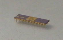
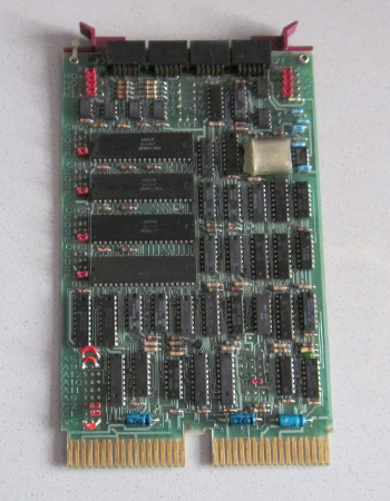
Picture 1 - My first piece of real old PDP-11 hardware was this micro code ROM of the LSI-11 chipset. It is the oldest of my collection, manufactured mid of 1977. Origin is from an electronics scrap company which sells salvaged chips. Despite of a minor crack in the ceramic case, it's still running.
|
From an engineering point of view, the PDP-11/03, first produced in 1975, is more interesting than modern models of the PDP-11. That's because it's more similar to the first PDP, the 11/20 of 1970. Despite of the large- scale integrated chips of the CPU (4 or 5), the missing MMU, the limited 16 bit adress space and the FIS and EIS instruction set extentions (rather than implementation of a math coprocessor) are quite clear properties.
There is not that much information about the little old 11/03 in the web. A lot of fans saved one of the grand old classic 11/44 or 11/45 from the trash can, running them and their websites wih much enthusiasm (see links). Also a PDP-11/23 is found in a lot of private collections. 11/03 aren't presented that often, even if so much were used as machine controlers. That's the reason I put my experiences on a website.
Acquire old hardware
The first plan about old 11 hardware was to have frequent looks to the electronics scrap companies for LSI-11 chips. With a bit of luck soon I would have had a complete set. The LSI-11 CPU has multiplexed adress and data lines, so using some of my old SRAM chips a kind of very primitive computer similar to the Mark-8 (Intel 8008 based hobbyist construction of 1971) would have been the result. But before I had all the chips, I found out about the modules I use now. Needless to say I didn't stop collecting the chips so I now have four complete sets including FIS/EIS microms in working condition! See a table of chip numbers I have tested (they run in all combinations I tried):
| LSI-11 chip | DEC No. | Western Digital No. | processor logic blocks |
| 1611H Data Chip | 21-15579-00, 21-16890-00 | AB1611-A00 | internal data bus, ALU, register set |
| 2007C Control Chip | 23-002C4-00, 23-003C4-00 | AB1621-A07 | state machine, instruction decoder |
| 3010D Microm 1 | 23-001B5-00, 23-008B5-00 | AC1631-A10 | microcode for standard instruction set (part 1) |
| 3007D Microm 2 | 23-002B5-00, 23-007B5-00 | AC1631-A07 | microcode for standard instruction set (part 2) |
| 3015D optional EIS/FIS | 23-003B5-00, 23-009B5-00 | AC1631-A15 | optional microcode for "Extended Instruction Set"
and "Floating-point Instruction Set" |
|
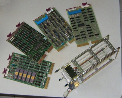
Picture 2 -
The Qbus modules I acquired in 2009 as "spare parts in running condition". Left to right:
M7270 LSI-11/2 CPU (optional EIS/FIS microm originally missed but already plugged in at the photo),
M8044 MSV11-D 64 kByte RAM,
M8017 DLV11-E serial interface; finallyI got a
M7946 RXV11 floppy interface (right).
Foremost the backplane, a H9281-BA (four dual slots). At the power terminals I already attached a PC-PSU compatible plug.
|
Assembly of the modules isn't much of a problem. Rule #1: the CPU has to be put into the first slot of the backplane (component side visible from frontside). Rule #2: there must be no voids between modules. So for a first test I plugged in CPU, RAM, serial interface and left the last slot empty.
A little bit of soldering is necessary until this absolute minimum configuration of a PDP-11 gets alive. Power is taken from a salvaged PC PSU. The LSI-11 CPU wants a certain power-up cycle, so I set up a small external board which is plugged to the 10-pin connector at the backplane. Circuit is close to the suggestion from the DEC manual [1]. There also can be found the pinout of the backplane plug.
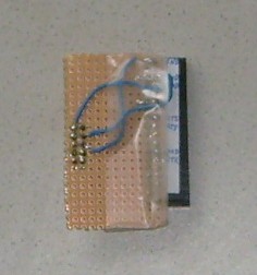
Picture 3 -
The small control board with 3 switches and 3 LEDs. Absolute minimal configuration would be two switches for "DC OK" (debounced, switches to logical "high") and "HALT" (switches to ground). At the photo, the third switch is for LTC enable. Three LEDs show PSU power, "SRUN" signal and "HALT". TTLs are for debouncing.
|
|
|
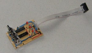
Picture 4 -
Just a bit missing for successful communication: the proprietary DEC-plug on the module board has to be patched to a standard serial plug. This is done by the little patchboard and 3 wires (TxD, RxD, ground). I soldered them to a plug which also is present in PC motherboards so I can use a standard cable. Not visible at the photo is an interlock at the DEC connector.
|
Configuration of the serial interface is easy, if you've got one of the old "console terminal" boards. Console must use IO port (octal) 177560 and interrupt vector 60. So if you're not so lucky (as I was) you have to re-jumper the module. Revisions of the boards aren't identical, so I needed quite a lot of research at the web to find the right manual for mine. It turned out what I have actually is a DLVE1, which is a newer revision of (and logical compatible to) the DLV11-E. It has been used as modem interface in 11/23s and some VAXs with Qbus slots.
Old DEC modules are jumpered by wire-wraps. Unneccessary to say nobody today has proper tools for this stuff. However, the pin separations are standard, so a common IC socket can be converted to a number of jumpers.
BTW, don't forget: today's quasi standard for serial ports also should be set by the jumpers. Most PCs serial ports are default configured like this: 9600 baud, 8 bit, no parity, 1 stop bit, no handshaking.
After the 2012 desaster with the floppy emulator I started to think about which kind of interface still makes sense for old computers. Experiences of people as well as mine show that the silicon itself is nearly immortal if handled properly. Some people contacted me about a replacement for their dead DEC PSUs (obviously, my comments on the small adaptor board weren't that clear to some). Most old computers are thrown into the dumpster for dead external storage media. Thus, disk controllers don't make any sense - also due to the problems with emulation.
There is only one type of interface which is native to both architectures (oldie '11 vs. modern PC): RS-232. Serial Qbus cards are easily found, and the modern serial-USB converters work well under most OSes I saw on the PC. And, there is at least one storage media which was attached via a serial interface (the TU-58 tape drive), meanwhile a number of emulators for the PC operate quite successful. It's even possible to boot a PDP-11 this way as has been shown for some OSes, as XXDP or RT-11.
Of course, tape emulation is slow. But the oldies are not any longer a tool for daily work. So time doesn't matter so much.
Testing a minimal System
A first test run should start with a proper PSU voltage check - no problem if a PC PSU is used. Original old PSUs should be tested before, of course. Next we need is a second (modern) computer running a terminal emulator. I guess no one of use yet has access to a real old VT-100 or something like it. Connect the terminal emulator serial port by a null modem cable to the 11/03.
Before applying power, all switches on the control board are set open/off. Power up PSU, then switch "HALT" and next "DC OK". The terminal emulator immediately should reply something like
000000
@
Now we're in ODT (Octal Debugging Technique) mode, a hardware debugger built in to the CPU. It's a more modern version of lightbulbs and switches the old mainframes of the 1960ies and 1970ies had on their front panels. By it, you can test and set contents of registers and memory or toggle in short test programs or read in absolute loaders (at least if you still have a punched tape reader). The processor itself isn't running in ODT, i.e., its program counter isn't incremented. Modern CPU chips doesn't possess anymore such elementary diagnosis tools.
ODT is somewhat cryptic to handle. It doesn't wait until the user (operator) finishes an input line by "enter", but scans every typed key. Every number key outside the octal range 0-7 is immediately rejected by a "?" error message. To examine memory locations, type the octal adress followed by the "/" key. ODT then returns in the same line the content of the memory location. Still in the same line, it waits for you to set up a new value. If you do so and finish by "enter", you're back at the "@" prompt. If you press "linefeed" (on a modern PC which hasn't a key for anymore, use "control-j" instead), ODT closes the line and opens the next memory location in the next line. If you don't input a new value, the memory value displayed is preserved. Registers can be examined and set by entering "R0" to "R7" followed by "/" at the @ prompt.
Octal program code can be run by entering the start adress followed by "G" (must be capital g). Open the "HALT" switch prior to this.
|
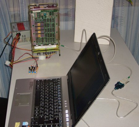
Picture 4 -
First life sign of the PDP-11/03 seen on the left. LSI-11 chips on the first module are clearly visible. Behind the backplane sits the PC PSU on the table. Foreground shows the notebook of my girl-friend which runs the terminal emulator.
As I performed this first test, the optional EIS/FIS microm wasn't plugged in yet.
|
Website "Hints on testing a dead PDP-11" (see links) has some very useful tips how processor and memory can be tested. The first "program" I tried was octal 5007 at memory location 0. It is just a "clear PC" instruction which obiously loops at location 0. A 777 (branch -2) does the same but can be put to every memory location where the processor then loops endlessly.
If doing some more complex things than one-instruction-programs, some initialzation should be done before. This helps to prevent some misleading breaks. Certain error conditions trigger traps (fixed interrupts). Their vectors should keep default values, same is valid for the stack pointer. Imagine we try to run a program which has some invalid octal instruction in it. Reaching it, the processor will trap into an "illegal opcode" - PC and status are pushed to the stack, and the new PC is loaded from location 10. If the stack pointer is not initialized, it possibly points somewhere to non-existing memory. So, at the moment the processor tries to save its old PC it traps into a "bus error". This may be annoying in testing basic functions.
Program execution always stops if instruction code is 0 (halt). Normally it is the last instruction in short octal test programs which returns control to ODT. Empty memory location very often also contain 0's - a jump to somewhere in memory, mabe by an uninitialized trap vector, usually also halts program execution (but don't rely on that!). A trick I use is to use the adress of the trap vector minus 2 as the trap vector and put there a 0. ODT then returns exactly the vector adress of the trap if one occurs.
Obviously this works only for a valid stack. So, SP (or, R6) has to be set to e.g. 700 octal which is sufficient for short programs. Program code now can start at 1000 (no danger by stack which grows downwards).
Thus, the following is my start configuration:
000000 / 000000
000002 / 000000
000004 / 000002		<--- bus error
000006 / 000000
000010 / 000006		<--- illegal instruction
000012 / 000000
000014 / 000012		<--- T bit trap
adding just one more for floating point tests::
000242 / 000000
000244 / 000242
and initialzation of the SP:
R6 / 000700
and we are ready to toggle in our first program, maybe a memory test program (it stops by a bus error trap, then address of first non-existing memory location plus 2 is in R0, examine it by "R0 /"):
001000 / 005000
001002 / 005720
001004 / 000776
001006 / 000000
Same way the EIS/FIS extentions can be checked. Example below is for a FIS "fadd (r1)" instruction. If the optional microm isn't present or broken, the processor will trap into "illegal instruction" or "floating point". If all is well, the program loops endlessly and must be stopped by toggling the "HALT" switch:
001000 / 075001
001002 / 000776
Before running the example above it is important to set R1 to some sane value, e.g. "R1 / 002000" or there again is risk of a misleading bus error.
Same also works for an EIS instruction like 070202 (mul r2, r2). In this case R2 doesn't need to keep some meaningful value.
Emulating Old Floppy
NEWSFLASH: As of June 16, 2013, I got this running again. Find soon some more detail here. Hardware: Pentium III 650MHz, 100MHz FSB, 440BX northbridge, PIIXE southbridge, native parallel port @IO 0x378, BIOS setting "ECP". Software: Debian GNU/Linux 5.01 (DVD1 sufficient for install), Kernel 2.6.26, rxm compiled by gcc 4.3.
Rxm does not work with Debian 6.0, USB-parallel cables, and parallel port PCI cards.
There were a number of reasons why I didn't seriously look for an old floppy disk drive. Maybe 30 years old chips do still a good job (CPU and RAM do indeed),
a 30 years old mechanics hardware may have got some weak parts over time. Moreover, an old 8" FDD also requires an old 8" system floppy in working
condition. To get one may be a lot harder than simply download some disk images from the web. For example, to put together a boot floppy image using
SIMH emulator running RT-11 is a quite easy exercise. Finally - I also don't owe a VT100 terminal but use a PC running a terminal emulator.
So, a PC emulator of the RX01 disk drive was needed which is soon found via the web. Charles Dickman's free "rxm" (see links) emulates a RX01/RX02 drive via the
PC parallel port. A small circuit board adapter is needed to connect the PC port to the floppy interface card on the PDP side. The PC must have a
"real" parallel port (an USB-to-Parallel converter will not work) for rxm accesses the hardware addresses of the port.
I downloaded the adapter board schematics and used one of these universal experimental boards to solder all parts on. I did some minor modifications -
first, I replaced the NAND gate chips by a single 74LS04 hex inverter chip (which I had in my scrap box), and I also removed a number of the pullup and pulldown resistors. I left only
the 390 Ohm pulldowns at RX_INIT, RX_RUN, RX_DATA, RX_DONE, RX_TRANSFER_REQUEST and RX_SHIFT in place. (The reason was some extended
"debugging" of the kind I describe below). At the floppy interface card inside the 11/03 I again inserted a small
patchboard (similar to the one I use at the serial card) which is connected to the adapter board via a
premanufactured 10-wire connection.
Rxm I built from the source using gcc under Debian Linux 5.0. First the "Makefile" didn't run smoothly but it was
easy to find the correspondig compiler command inside it and copy&paste it to the shell. Direct hardware access
isn't allowed for Linux users - so the rxm binary has to run with root privileges. Can be done via setuid (log in as
"root", do a "chown root rxm" followed by "chmod 4755 rxm". Now all common users will be able to run rxm).
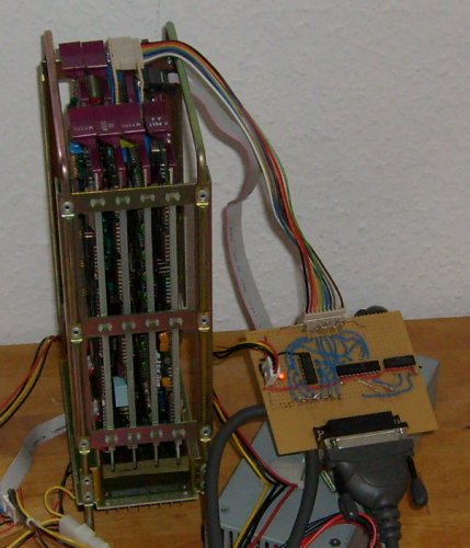
Picture 5 - the adapter board for rxm emulator plugged in between PDP-11 and PC. The Backplane of the 11/03 is visible from left side at the photo.
Meanwhile I also acquired a smaller PSU (100 Watts are sufficient). It's small enough to fit into a case later. The PSU is hardly visible under all the cable stuff next to the adaptor.
|
|
For a first test, start rxm in highest verbosity level by "rxm -vvv -t RX01". Empty disk images will be attached
by rxm automatically.
At the PDP terminal I prepeared by checking if both floppy interface registers respond. At octal location 177170
is the control register RXCS, at 177172 the data register RXDB.
The very first test was to check if the init flip flop logic worked. To do so, I wrote octal 40000 into RXCS. On PC
side this resulted in a "RX_INIT request recieved" message. Reading RXCS now delivered octal 000040 which means
"done". So far all was ok.
Next test: a function command. Writing octal 11 to RXCS (a "NOP" command) should deliver a "RX_RUN request recieved"
at PC side together with the correct function code info and if 8 or 12 bit code were recieved (my RXV11 can do only
8 bit codes). At first this didn't work the correct way and was the reason why I started to try about removing
resistors. When all worked ok, reading RXCS in the end again showed octal 000040 "done".
Proceeding this way I took more complicated tests step by step. Next was function code octal 7 to RXCS (a "read
sector" command) which resulted in a "transfer request" as reply (reading RXCS shows octal 000200). Now I wrote a
sector number (1-26 decimal) to RXDB, and same once again for track number (0-76 decimal). In the end RXCS again was
000040 "done".
Same way all the other of the function codes described in the manual [6,7] can be checked. Some of them are boring
(for example, the sector buffer is transfered byte by byte through RXDB). However, some simple test pattern can be
written to the disk this way. The latter can be checked for by the "od" Linux command typed at the shell.
The last test I did was typing the boot code which is printed in a number of manuals (including [7]) into the 11/03.
As expected, it worked up to the point where execution was transfered to location 0. Of course, of an empty disk
a zero boot sector of 128 bytes was loaded which halted the processor when trying to jump into the (non-existant)
bootstrap code.
However, the correct function of emulator and adaptor was proven at this point. At least it was 2009. As mentioned above, in 2012 it didn't work anymore.
Emulating Old Tape
Back in their great times, PDP-11s occasionally were run by TU-58 tape drives. These drives didn't have much space (256k), were quite slow but had the big advantage they needed no special controler PCBs. TU-58s were plugged into a common serial interface. For us modern hobbyist this means no more soldering of special hardware but just the need for a plain old null modem cable between modern PC running an emulator and old PDP.
Today, modern PCs no longer have serial interfaces. But there are serial-to-usb adaptors available which are well supported by the common OSes. For me it's Linux, and the Linux kernel automatically recognizes the two adaptors I use as /dev/ttyUSB0 and /dev/ttyUSB1. Normally I plug /dev/ttyUSB0 into the console interface and /dev/ttyUSB1 into the TU-58 interface.
Since the good support for the current adaptor cables and the fact that USB will remain a standard interface on PCs the next years I hope I will not get again the same problems as with the floppy emulation.
Picture 6 - Quad serial card DLV11-J was available at a reasonable price at the ElectricBay. However, I had to reconfigure nearly every possible jumper, as you see here (all the red stuff is my work). I set it back to factory mode, with RS-232 mode, 9600 baud, 8 bits, no parity, 1 stop bit, IO port 176500 (octal), vector 300 (octal), use port 3 as console (177560, vector 60).
After the rejumpering, the card worked flawlessly on all of the ports.
|
|
|
It's quite easy to fit the pinout of the interface plugs to a 9-pin-SUB-D. One just needs the three lines RxD, TxD and common ground. Sub-D plugs and two-row sockets in 2.54mm raster are supplied by common electronic stores. I used a very flexible microphone cable for the three leads between the plugs. It has two lines for RxD and TxD and a shielding (used for ground).
|
As done earlier, first test very well can be done using ODT. Just plug in the second serial line and start a second terminal emulator at the port (/dev/ttyUSB1 for me). Then it is quite easy to enter some test commands on the console and watch out what happens on the second terminal. An example: if /dev/ttyUSB1 is connected to serial port 0 of the PDP, it is possible to enter an octal value at the corresponding transmitter port address and watch out how a char appears on second terminal:
176506 / 000102
will generate a 'B'. Thus, all port adresses can be checked quite comfortable.
Same way it's easy to check for correct interrupt vector. On the '11, toggle in a short program:
1000 / 012700         <--- r0 = reciever csr
1002 / 176500
1004 / 012760         <--- set in rec. csr "interrupt enable"
1006 / 000100
1010 / 000000
1012 / 000777         <--- endless loop
Of course, as was in a preceding chapter, some housekeeping is neccessary here, too:
276 / 000000
300 / 000276
302 / 000000
304 / 000302

R6 / 000700
set up a correct stack and the interrupt vector table needed. If the program now is run by a "1000G", the 11/03 will loop at location 1012 until a key is pressed at the second terminal. In that moment the program should stop at location 000300 and we're back in ODT.
Same way all the other values can be tested. Factory settings are port1: 176510, vector 310, port 2: 176520, vector 320 (all octal). Port 3 is console.
If the hardware layer is running correctly, it's time to look upon the emulator. I downloaded ak6dn's tu58em (see links). Builds without problems under Linux, just when executing there is an issue: definitions in system header file termios.h seem to be not the same under all OSes. On my PC (running Debian GNU/Linux 6.0), the baud rate isn't set at all if tu58em initializes. There is a simple workaround for it: just open a second command shell AFTER tu58em has been started. Then set the speed manually on it by typing "stty -F/dev/ttyUSB1 9600" (put the values you use in here) on the second shell. Then all works well.
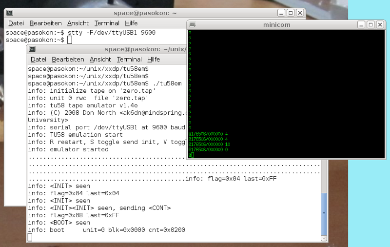
Screenshot - Here you can see a simple manual test of tu58em. Console (at /dev/ttyUSB0) runs in the green-black xterm window. Looks quite stylish 70ies, doesn't it? :)
Below it the shell which runs tu58em on /dev/ttyUSB1 at port 0 of the PDP. Was started by "tu58em -v -d -p /dev/ttyUSB1 -c zero.tap" which emulates an empty tape (zeroes) and puts out lots of diagnosis.
Behind the tu58em shell you see the second shell were I typed the baud speed stty command after tu58em started.
Using ODT I sent commands to the emulator via the transmitter register of port 0. In 176506 I toggled in 4 (init), 4 (init), 10 (boot) and 0 (boot drive). Below you see the replies of tu58em. A twofold init causes the reply of a "cont", and the sequence "boot 0" causes it to start the transmission of the 512 bytes of block 0.
|
|
Of course this can be put in a small program which works as a simple tape bootloader. A note: in the web quite often the bootloader from the DEC TU 58 technical manual is cited. I tried it, it didn't work for me. tu58em recieved just a "null" and then everything hang. I was not in the mood to copy the ROM boot code (for legal reasons as well). Thus I set up my own boot code (source code for pdp11-aout-as crossassembler you may find here):
1000 / 005000     <--- r0 = 0               (bootloader standard)
1002 / 012701     <--- r1 = reciever csr    (bootloader standard)
1004 / 176500
1006 / 012702     <--- r2 = transmitter csr (bootloader standard)
1010 / 176504
1012 / 012761     <--- send "init"
1014 / 000004
1016 / 000006
1020 / 005761     <--- wait until sent completely
1022 / 000004
1024 / 001775
1026 / 012761     <--- send "init"
1030 / 000004
1032 / 000006
1034 / 005761     <--- wait until sent completely
1036 / 000004
1040 / 001775
1042 / 012761     <--- send "boot"
1044 / 000010
1046 / 000006
1050 / 005761     <--- wait until sent completely
1052 / 000004
1054 / 001775
1056 / 012761     <--- send 0 (drive no.)
1060 / 000000
1062 / 000006
1064 / 005761     <--- wait until sent completely
1066 / 000004
1070 / 001775
1072 / 105711     <--- wait until reply recieved completely
1074 / 001776
1076 / 116105     <--- ...and flush it (was the "cont" reply)
1100 / 000002
1102 / 005003     <--- r3 = 0 (byte counter)
1104 / 105711     <--- wait until byte recieved completely
1106 / 001776
1110 / 116123     <--- move to memory, increment r3
1112 / 000002
1114 / 022703     <--- r3 = 512?
1116 / 001000
1120 / 001371     <--- if not, continue ...
1122 / 005007     <--- ... else jump to boot block
By this small program (BTW, it's GPL - have fun!) one can do nice experiments. I loaded zeroes from the "zero.tap" (see above) as well as byte patterns from other image files successfully this way. Just depends on what tape image you plug into tu58em.
In the web there are a a number of TU-58 tape image files of ancient OSes, most of them for XXDP. Couldn't find out who owns the rights on it today (HP? Mentec?). Nearly all freaks seem to use it and don't care about licenses. Is it "abandonware"? If you know about, please drop me a short note...
I'm quite sure XXDP would boot also on my PDP-11/03 using tu58em. A number of people out there already did so.
Toolchain for kernel build
Introduction
As I mentioned above, in the 1980ies a PDP-11 running Unix was kind of Holy Gral for a common hacker. Today, the old Unixes are free for private noncommercial use. Thus, I wanted it to have for my 11, too. There is a version able to run on an 11/03: the "LSI_Unix" or LSX. In 2009 when I first wrote this section I didn't know about - and started to look for a free small Unix clone.
Of course, this section remains valid for building a LSX kernel, too.
Current work on LSX I do with gcc 4.7.1 and binutils 2.22. Note that pdp11-dec-bsd support isn't longer there, so you have to build for pdp11-aout target.
Xinu
So [in 2009] I continued my quest for a free operating system. Unix in the 1980ies was cloned a few times (when
AT&T didn't permit any longer the use of the source for educational purposes). GNU, Minix, Xinu and
finally Linux were born this way. Except Xinu, all of these want to have a MMU hardware and off they
are.
About Xinu a detailed description is in Comer's book [9] which is one of the best books on operating
systems I know. Xinu itself, originally written for the PDP-11/03, is more or less an embedded OS. For file operation
it has a lot of network suppert. The latter I don't need for I have no DEQNA. On the other hand, here
is my not supported emulated RX01 disk drive. Cannot be so hard to write drivers for it. Excercises
like this were the exact purpose of Xinu when it was designed.
The last version of Xinu includes a shell which has some internal commands for playing a little bit
"user". (A sidenote: reminds me to my early tries about a minimal Linux some years ago. It was before the
Live-Linux-CDs of today. I set up a PC boot floppy which contained only monolithic kernel and "sash"
standakone shell.)
Concerning Xinu, finally I don't want to do real program development on the 11/03, it's just to run some
code for fun from time to time. So, a "half-embedded" OS with crosscompiler on a host is ok for me.
Xinu source tree in its original form was for PDP-11 only and contained a SDK (cross-cc etc.). This
branch is not any longer maintained.
so my first tries were about reanimation of the old SDK. Long time ago, it ran on VAX under 4.3 BSD.
Differences against modern Linux distribution were too big to get anything usable here. Just nm11
compiled but as far as I can guess it didn't run.
Gcc toolchain
But in the end I needed just the Xinu sources itself. Crosscompilers can be found elsewhere - for
example, GNU C can be built as crosscompiler, even if that seemed not to be a really simple task. Meanwhile
there are also websites about gcc crosscompiler building, see links.
I used binutils-2.19.1 and gcc-core-4.3.3 which were downloaded from gnu.org. Both of them don't
like to be built from their source directories, so each of them got its own working directory
with a subdirectory src/ in it. The tar.gz was unpacked to the latter. Binutils then builds by:
src/configure --target=pdp11-dec-bsd --disable-nls
make all
make install
(last step of course as "root"). For gcc I needed on my Debian 5.0 libgmp and libmpfr including
devel-stuff. Note that libmpfr-dev is not on the Debian DVD but has to be downloaded from debian.org.
Changing to its own working directory, gcc builds with:
src/configure --target=pdp11-dec-bsd --disable-nls --without-headers --enable-languages=c
make all-gcc
make install-gcc
Only remaining problem is libgcc, which won't build. Maybe it's a problem about the gcc assembler output,
by default it does "unix-asm" but GNU assembler wants "dec-asm". Bug or feature? I didn't want to patch gcc
(way to "nerdy" for me) but decided to proceed without libgcc (see below). When running gcc, I have to use
the -mdec-asm option by default which works well for me.
{Postscriptum: in 2009, cc compiled the logical AND "&" errorneously
to the "BIC" assembler instruction (cf. [8]). I did a report about via gcc bugzilla, and as of gcc 4.7 it's fixed. However, for historical reasons I leave my gcc 4.3.3 patch here for reference... the patch and how to apply it you may find here. Once again: for the actual version of gcc, it's not needed anymore.}
Old C code and modern compiler
The case about the missing libgcc isn't that terrible. At least not if you're compiling for a PDP-11
which has EIS/FIS support. Gcc generates much native code for such hardware. And if we suppose the Xinu
kernel to be running code, everything else neccessarily has to be found in its sources.
If one tries to compile the Xinu C libraries libsa.a and libxc.a, together with the demo.c program,
just 32 bit signed and 16 bit unsigned division and remainder (function calls "___divsi3", "___modsi3",
"___udivhi3" and "___umodhi3") are reported as missing by the linker. The corresponding library
functions are in ldiv.s and lrem.s for which a few lines of assembler code provide a nice little wrapper.
Finally just "___main" is missing, which can be done by a simple "rts pc" assembler instruction - Xinu is
all-static, we do not need constructor code here.
The demo.c program now is linking. Later I decided also to drop in the unsigned long division and remainder,
which can be borrowed from gcc source "udivmodsi4". Just to be complete.
Float didn't work at first, gcc generates code for the 11/40 FPU only - variables aren't initialized,
code doesn't look trustworthy to me... the option "-mfis" also doesn't work so I set up a little library libfis.a
which uses the FIS extentions of the LSI-11 processor. Finally I also got float.
BTW, it's going deep into the dungeons of pre-ANSI-C if you try to compile Xinu source files. You'll find "=/"
operators (instead of "/="), function prototypes aren't defined in the files and so on. But all this is
easily updated to the modern rules of C.
Assembler has changed, too: normal numbers are decimals today (not with a "." at the end), octals have
a leading "0" today.
Download of the binary
It's quite easy if one reminds how the real old 11's were connected via serial interface to teletype
terminals (TTY). The latter very often had a built-in punched tape reader. After starting the PDP a
short boot loader was toggled in via console switches or ODT. The bootloader then read the punched tape in.
Today it can be done in a quite similar manner, after typing the bootloader it is started via the ODT "G"
command (see above). Stop the terminal emulator by shortcut ("Ctrl-A" and "Q" for minicom). Because now the bootloader
"listens" at the PDP serial line, the program binary is just copied to serial:
cp demo.bin /dev/ttyS0
(of course permissions have to be set in a right way to do so).
Now start minicom again, stop the bootloader loop by the "Halt" switch on the 11/03 and then start the just
downloaded program by the ODT "G" command.
Short punched tape bootloaders can be found on various site on the web, I've got mine from YAPP (see links).
Very versatile, start address to which the binary is downloaded can be put into 157766 (for linked Xinu
binaries always 0). After download the octal number of bytes read is in 157752. This can be cross-checked on the
host (e.g., by the "od demo.bin" command) to assure the right number of bytes has been transmitted.
The bootloader is relocable, i.e., it can be shifted to another RAM address to assure it's not overwritten
by the main program execution. Doing so, the bootloader can be recycled after reset of location 157752
(or, its equivalent) to zero.
157744 / 016701
157746 / 000026
157750 / 012702
157752 / 000000    <-- offset (counter)
157754 / 005211
157756 / 105711
157760 / 100376
157762 / 116162
157764 / 000002
157766 / 000000    <-- bank (RAM start adress)
157770 / 005267
157772 / 177756
157774 / 000765
157776 / 177560
Debugging with ODT
Now as we've got a binary in the 11's RAM, is started - and of course crashes. Rudimentary debugging can be done by the ODT
console commands (after all, it's a hardware debugger), even it's not that comfortable. Diving to the abysses
between bits, I've found out Xinu libs and gcc didn't agree about the stack frame size. The latter can be fitted in
csv.s (just subtract 2 to the sp in the right place in function csv). Thus at least the local variables worked in a correct way.
Other issue was hardware IO check of status registers. Gcc does optimizations which remove the query loops
if the variable declaration isn't done "volatile". Fitting all this I finally got the demo.c program with
libsa.a library running really on the PDP-11/03 hardware. Thus, at this point I have a really functional C toolchain. A great jump in the right direction.
|
Picture 6 -
Doesn't look like much, a "hello world" and some integers. But finally here runs formatted output by printf() which in itself is a quite complex function of the C library.
|
Yet finally... UNIX!
Introduction
Rambling the Web in my summer holidays in 2012, I finally found there really WAS an Unix variant for the PDP 11/03, too: LSX (abbreviated for "LSI-UNIX"). It is a still more stripped-down version of Mini-Unix which in turn was an adaption of Unix V6 to machines without MMU. While Mini-Unix can serve four users at once but still needs a RK05 hard disk, LSX serves only one user and fits onto two RX01 floppies. It already can run in 40kB RAM and of course also needs no MMU. Nevertheless it's a complete OS including a C development kit. More than I was longing for. 30 years later, the Holy Grail, finally just before my eyes!!! :)
LSX was developed in 1975. It never left the Bell Labs (knows anybody why?). Until 2004, when two floppies appeared on a vintage computer festival it was lost. 2006 Leonid Broukhis fixed the saved floppy images and made them boot again.
If history went just a little bit different, we would have had a Unix "11/x" PC in 1976. And all the "x86" computer stuff and Windws were nothing but a bad dream. (Sadly, also Linux.) And nobody knew who the hell are Steve Jobs or Bill Gates...
Because it's a derivate of Unix V6, LSX is covered by the Ancient Unix License. Moreover, Mr. Lycklama, the author of the patches, has given his work (and permission of use) to the PDP Unix Preservation Society. Thus it is - as far as I currently see - free for private noncommercial use.
Download of the LSX floppx images (including C compiler and sources) is on Leonid Broukhis' LSX Unix Restoration page [10] (see links). There also is some instruction how to get LSX booted under the SIMH PDP-11 emulator.
A hint from me: by default, LSX expects uppercase letters as input. Thus, on the boot prompt, type not "lsx" but "LSX" or else SIMH will stop with a HALT.
Documentation about LSX is very sparse. You have to keep close to the Unix V6 manuals - just remind a lot of nice stuff simply isn't present under LSX. A paper about LSX exists [11] and an internal memo about Mini-Unix [12] which both give hints on some LSX specialities and some patches of some of its programs.
Concept
Thought a bit about other storage media to attach to the LSX kernel. RX01 floppy isn't available any more. TU-58 over serial seems a way to go. There is just a driver to be ported (for TU-58, there is one in 4.2BSD Unix). There are lots of TU-58 PC emulators out there which are regulary used even for booting old PDPs.
A TU-58 tape has same amount of storage as a RX01 floppy: 256kB. So, a LSX root file system should fit onto it. All the "dirty" work of file system image preparation could be done with SIMH.
However, SIMH disk images are plain 1:1 sector copies of all floppy sectors, including also the sector interleave of 3. It's quite easy to write a converter to get proper plain block images (which can be used as tape images), but the sector interleave also is hardcoded in the bootloaders. Thus, they can't be used for a TU58 root file system.
Nevertheless the block image file of the root.dsk looked quite sane. Checking with od I found super block, inode list and root directory are in the places where to be expected (I learned during my studies how a Unix file system should look like). Thus, LSX takes the same route as was planned in 2009 for Xinu: crosscompile the kernel sources on a PC, upload the kernel via console paper tape bootloader, and attach a prepeared file system image via an emulator. Just this time the hardware interface will be a second serial interface.
LSX kernel crosscompiling
Adaption of the kernel sources to modern gcc was essentially the same as it was for Xinu (see above). I fitted the source files one after the other. Just the 4.3BSD driver tu.c needed some more care. A number of things did change since the days of Unix v6. Finally it compiled, too. Main problem is its size which is substantially larger than the floppy driver it will replace. The final kernel binary had 21.6k (bytes). Thus, the start of the userspace can no longer stay at octal 40000. This means all the programs in the file system have to be rebuild, too.
I chose now 24k for kernel, 32k for userspace. RAM today is not an issue for most old Qbus machines. So I also gained some room for short diagnosis messages of the kernel. I hacked a simple "printk()" for text only which sends some startup messages and also some debug info should a panic() occur.
A kernel binary this way builds successfully on my PC.
Will be continued!
Appendix: PDP11 on PC PSU howto
The last months I got a number of emails from (more or less) desperate PDP-11 owners with a dead DEC PSU, I now give here some more info how to connect a PC ATX PSU to an '11 backplane. I did it this way on my 11/03 but it should work same way at least for other Qbus machines.
First part is simple. The backplane has some power terminal with required voltage values printed next to it. Corresponding voltage values of a PC ATX PSU are color-coded::
| yellow | +12V |
| red | +5V |
| black | 0V (GND) |
The -12V terminal can be left open, it is not required for the PDP-11 itself (but beware of some of the peripherals - read your manuals!!!).
I cut off the 4-pin "male" connector of a PC HDD power cable (you can get such from any of the major electronics and PC part sellers), striped the insulation off the wire ends and screwed it to the backplane terminal.
Caution: PC PSUs have an interlock at the connector for the PC mainboard. It is the green cable, should be connected to ground (black) to enable the PSU.
Second part is about a 10-pin connector close to the voltage terminal on the backplane. One of the pins is missing to avoid accidental reverse plugging of the cable. Some of these pins have to be switched in a certain sequence to give the CPU a proper start.
Pins of the 10-pin connector:
 |
| BDCOK | most important. After the PSU has reached a stable operating state, this pin is pulled to logic "1" (Bus signal standard +3.4V, abs min value due to DEC manual +1.7V) This signal MUST be debounced. |
| BHALT | if this pin is pulled to logic "0", the CPU stops execution and changes to ODT mode. Console terminal issues an octal number and the @ prompt. |
| BEVENT | pulling this one to logic "0" generates an interrupt in the CPU. Can be left open in minimal configuration. The DEC PSU supplies the LTC input via this pin (Line Time Clock, 50Hz/60Hz timer interrupt, rectangular signal of +3.4V). Some operating systems probably won't start without it. |
| BPOK | can be left open. Similar to a second BDCOK. |
| SRUN | back signal from the CPU if it is in running mode, executing program code. Can be used for a LED on the front panel. If I remember right it's inverted (CPU running issues a logic "0"). |
| GND | common ground for reference. |
|
Debouncing of a signal can be done by two common inverters (due to DEC manual, 7404, 74LS04, 74HC04 or whatever is currently compatible to these old types). A 7404 chip contains six of them. The resulting output has to be converted from TTL +5V logic to DEC Qbus +3.4V logic. In the most simple case this can be done by a voltage divider. I used a 47 Ohm resistor in series. Maybe this is not a sufficient value, take a measurement at your backplane!
A better solution would be a proper voltage divider or a 5V/3.3V bus driver chip. (If some micro electronics guy can hint me a better solution I would greatly acknowledge it!)
Update: The 11/23 CPU manual has some info about (I found one in the big internet flea market). Bus lines have to be terminated by 120 Ohms. Since the switch in the schematics pulls directly to ground I changed the resistors accordingly, still works fine.
The debouncing is a must for the BDCOK signal only (just an option for the other) but since there still were inverters left in the 7404 I also used it for the BHALT signal.
|  |
Starting sequence:
1. BDCOK switch "off", BHALT to "on" or "off" depending on if you want to enter ODT mode.
2. Switch on PSU.
3. BDCOK switch "on". The '11 should now be up and some output become visible at the console terminal.
Absolute minimum for such tests are only three components: CPU, memory (sometimes on a common PCB) and the console terminal serial interface. All PDP-11 CPUs which support ODT should be able to work in some way with it. I suggest to do it this way as a first test to keep collateral damage in case of a severe error as minimal as possible.
=== DO AT OWN RISK! I SUPPOSE YOU KNOW WHAT YOU'RE DOING! ===
Links
PDP11.org --
Dedicated to preserving the history and legacy of the
PDP-11 series of 16-bit minicomputers.
Wikipedia -- Wikipedia's page about the good ol' 11.
hampage.hu/pdp11 -- This page is intended as a tribute to one of the most famous computers: Digital Equipment Corporation's PDP-11 series.
bitsavers.org -- Bitsavers, rich reservoir of software and documentation of old computers.
YAPP -- Yet another PDP page - contains "Hints on testing a dead PDP 11".
SIMH -- the SIMH emulator.
RXM -- Charles Dickman's RXM emulator page.
Building gcc -- Page about building gcc as a crosscompiler.
LSX -- Leonid Broukhis' LSX Unix Restoration webpage
Unix v6 man -- Online Unix V6 man pages
TU58 -- AK6DN's TU58 Emulator Seite.
*
References
[1] LSI-11, PDP-11/03 User's Manual. EK-LSI11-TM-002, Digital Equipment Corporation, Maynard, Massachuchets, 1975.

[2] M7270 LSI-11/2 Microcomputer Module User's Guide. Digital Equipment Corporation, Maynard, Massachuchets, 1976.

[3] MSV11-D, -E User's Manual. EK-MSV1D-OP-001, Digital Equipment Corporation, Maynard, Massachuchets, 1977.

[4] DLV11-E and DLV11-F Asynchronous Line Interface User's Manual. Digital Equipment Corporation, Maynard, Massachuchets, 1977.

[5] RX02 Floppy Disk System User's Guide. EK-RX02-UG-001, Digital Equipment Corporation, Maynard, Massachuchets.

[6] RX01/RX02 Pocket Service Guide. EK-RX012-PS-002, Digital Equipment Corporation, Maynard, Massachuchets.

[7] RX02 Floppy Disk System User Guide. EK-RX012-PS-001, Digital Equipment Corporation, Maynard, Massachuchets.

[8] Rapid Recall LSI-11, PDP-11/03, LSI-11/2 Reference Card

[9] Comer, D.: Operating System Design: the Xinu Approach, Prentice Hall 1984.

[10] Broukhis, L.: LSX Unix Restauration. http://www.mailcom.com/lsx/

[11] Lycklama, H.: UNIX on a Microprocessor. Bell Labs 1976. http://www.alcatel-lucent.com/bstj/vol57-1978/articles/bstj57-6-2087.pdf

[12] Lycklama, H.: Memo on Mini-Unix (Bell Labs, internal). https://www.msu.edu/~mrr/mycomp/terak/termubel.htm
Created: Apr. 18, 2009
© 2009 Diane Neisius